Isolated Induction Generator:
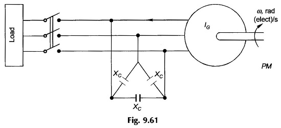
An Induction Machine can also work as a generator even if external power supply not available and it is called Isolated Induction Generator. An Isolated Induction Generator feeding a load is shown in Fig. 9.61. The delta-connected capacitors across the generator terminals provide the magnetizing current necessary to excite the isolated generator. The voltage build-up will be explained later in this section. As the generator is loaded, the operating frequency depends primarily upon rotor speed but is affected by the load, while the voltage is mainly decided by capacitor reactance (XC) at the operating frequency.
Let
- ω0 = rated frequency
- ωs = operating frequency
- ω = stator frequency corresponding to rotor speed
- a = ωs/ω0 and b = ω/ω0
The machine slip (which should be negative) can be expressed as
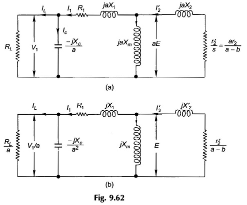
Assuming that the machine reactances, excitation reactances and machine induced emf correspond to the rated frequency (ω0), the per phase equivalent circuit of the system at operating frequency ωs = aω0 is drawn in Fig. 9.62 (a) with load considered as purely resistive. Dividing throughout by ‘a’, the circuit is reduced to the rated (fixed) frequency and is drawn in Fig. 9.62 (b).
Voltage Build-up:
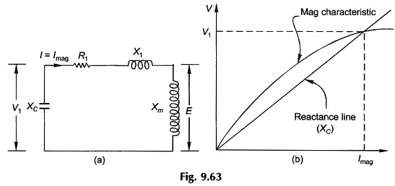
With reference to Fig. 9.61, consider that the generator is run at synchronous speed at no-load (switch off) with Δ-connected capacitors hanging on its terminals. The rotor circuit behaves as open and so the circuit model is as drawn in Fig. 9.63(a).
The current fed into the motor is I1 = Imag, the magnetizing current. If the voltage drop in stator impedance, R1, X1, is ignored, we have
Also
Like in a dc shunt generator, the magnetization characteristic and reactance line of Isolated Induction Generator are drawn in Fig. 9.63(b). Their intersection gives the no-load voltage. This is the case at rated frequency. V1 will vary slightly as the actual stator frequency changes from the rated value. This variation may be ignored.


