Ladder Type Converter D/A:
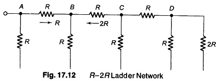
Looking into any load from the left side we always see a resistor R. Similarly looking from the right side for any load, one always sees a resistor 2 R. This impedance phenomenon is the key to analyzing a Ladder Type Converter D/A, as shown in Fig. 17.12.
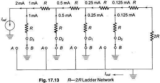
When the switch is to the right (B), as shown in Fig. 17.13, the upper ground is connected. When the switch is to the left (A), it steers the current to the lower ground which collects the output of the staircase.
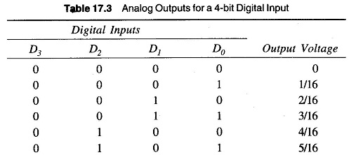
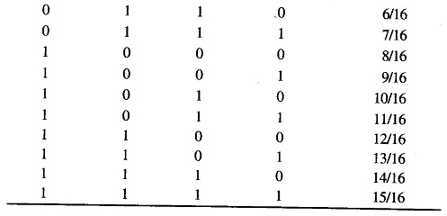
The output of a 4 bit ladder is from 0 — (15/16) Iref and each increment is of (1/16)Iref.
Similarly an 8 bit ladder produces a maximum output of (255/256)Iref. The LSB increment is then (1/255)Iref
The maximum resistance used is always twice the minimum At each node, there is a constant voltage or current; only the ground is changed. Due to this fact, stray capacitances have little effect and transients, that is exponential charge and discharge, are eliminated. This reduces the settling time and increases speed. Therefore, the ladder converter can be manufactured in bulk. Table 17.3 shows the various analog output levels for a 4-bit digital input.


