Large Signal or Power Amplifiers Articles:
Classification of Power Amplifiers: Classification of Power Amplifiers are primarily divided into two categories viz. audio power amplifiers and radio power amplifiers. Audio power amplifiers, also called the small signal power amplifiers, raise the power levels of signals that have audio frequency … (Read More)
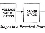
Various Stages in a Practical Power Amplifier and Block Diagram: Power amplifier is meant to amplify a weak signal until sufficient power is available to operate an output device such as a loudspeaker, a solenoid or a relay. Power amplifier, to … (Read More)
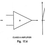
Class A Power Amplifiers (Direct Coupled with Resistive Load): A class A power amplifiers is defined as a power amplifier in which output current flows for the entire cycle (360°) of the input signal, as illustrated in Fig. 17.4. In other … (Read More)
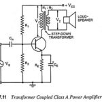
Transformer Coupled Class A Power Amplifier: Transformer Coupled Class A Power Amplifier also sometimes referred to as single ended power amplifier. The term “single ended” (denoting only one transistor) is used to distinguish it from the push-pull amplifier using two transistors. … (Read More)
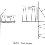
Class B Power Amplifier – Operation and Efficiency derivation: In Class B Power Amplifier operation, the transistor is so biased that zero signal collector current is zero. Hence class B operation does not need any biasing system. The operating point is … (Read More)
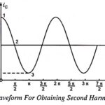
Harmonic Distortion in Power Amplifier – Waveform and Derivation: Harmonic Distortion in Power Amplifier – Output signal variations of less than 360° of the signal cycle are considered to have distortion. This means that the output signal is no longer just … (Read More)
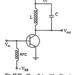
Class C Power Amplifiers – Circuit Diagram, Operation and Applications: A class C power amplifiers is biased to operate for less than 180° of the input signal cycle, as shown in Fig. 17.22. The tuned circuit in the output, however, will provide … (Read More)
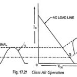
Class AB Power Amplifier Working Principle: In class AB power amplifier, the biasing circuit is so adjusted that the operating point Q lies near the cutoff voltage. During a small portion of negative half cycle and for complete positive half cycle … (Read More)
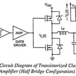
Class D Power Amplifiers – Circuit Diagram, Operation and Applications: Historically, audio amplifiers have been configured as class A, class B or class AB and the art of design is well known. Also well known is the poor efficiency of these … (Read More)
Push Pull Amplifier – Circuit Diagram and its Workings: As we know already that, double-ended or push pull amplifiers makes use of two identical transistors in a single stage. It consists of two loops in which the transistor collector currents flow in opposite … (Read More)
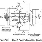
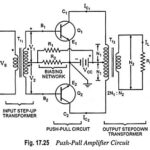
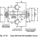
Class A Push Pull Amplifier – Working Principle, Advantages & Disadvantages: A Class A Push Pull Amplifier circuit is shown in Fig. 17.25. By Class A Push Pull Amplifier means that current flows in the output of the active device (each … (Read More)
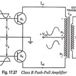
Class B Push Pull Amplifier – Circuit Diagram, Operation and Derivation: The circuitry for the Class B Push Pull Amplifier operation is the same as that for the class A operation except that the devices are biased at cutoff. The transistor … (Read More)
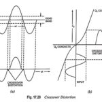
What is Crossover Distortion and how to eliminate it? In addition to the distortion introduced due to the nonlinearity of the collector characteristics and due to non-matching of the two transistors, there is one more source of distortion, that is caused … (Read More)
Class AB Push Pull Amplifier – Circuit Diagram, Operation and Drawbacks: The basic circuit of class AB push-pull amplifier is the same as that of class A push-pull amplifier shown in Fig. 17.25 except that the voltage drop across resistor R2 … (Read More)
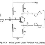
Phase Splitter Circuit for Push Pull Power Amplifiers (or Phase Inverter): In a push-pull amplifier circuit an input transformer is used to provide the polarity inversion between the two input signals to the push-pull circuit, but the transformer is quite expensive … (Read More)

Complementary Symmetry Push Pull Amplifier: The use of transformers, at input as well as at output ends, in the push-pull amplifier shown in Fig. 17.25 makes it bulky and expensive especially in this age of the integrated circuits. Another drawback of … (Read More)
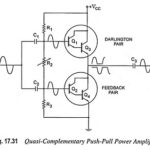
Quasi Complementary Push Pull Amplifier: In practical power amplifier circuits, it is preferable to employ NPN transistors for both high-current output devices. As the push-pull connection needs complementary devices, a PNP high power transistor is required. A practical means of having … (Read More)