LC Oscillator Circuit – Definition, Types and Equation:
Oscillators, which use inductance-capacitance (L-C) circuits as their tank or oscillatory circuits are called LC Oscillator. LC Oscillator are very popular for generating high-frequency outputs (e.g. 10 kHz to 100 MHz). There is a large variety of LC Oscillators such as tuned collector oscillators, tuned base oscillators, Colpitt’s oscillators, Hartley oscillators, Clapp oscillators, crystal oscillators etc.
General form of an L-C Oscillator:
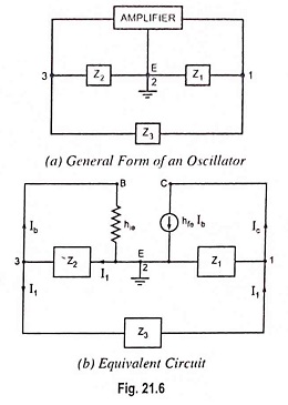
In the general form of an oscillator depicted in Fig. 21.6 (a), any of the active devices such as vacuum tube, BJT, FET or op-amp may be used in the amplifier section, Z1, Z2 and Z3 are the reactive elements constituting the feedback tank circuit which determines the frequency of oscillation. Here, Z1 and Z2 serve as an ac voltage divider for the output voltage and feedback signal. Thus, the voltage across Z2 is the feedback signal. The equivalent circuit is drawn in Fig. 21.6 (b) with the following two assumptions:
- hre of transistor is negligibly small and, therefore, the feedback source hreVout is negligible.
- hoe of the transistor is very small i.e. the output resistance 1/hoe is very large and, therefore, 1/hoe is omitted from equivalent circuit.
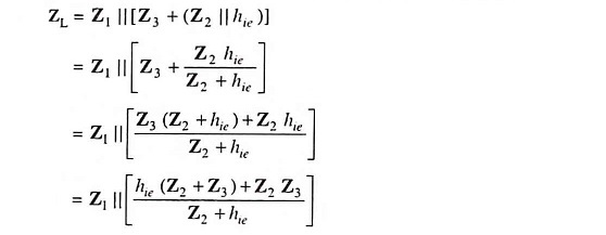
Let us determine the load impedance between output terminals 1 and 2. Here Z2 and hie are in parallel and their resultant impedance is in series with impedance Z3.
The equivalent impedance is in parallel with impedance Z1. Thus load impedance between output terminals is given as
or
or
The voltage gain of a CE amplifier without feedback is given as
The output voltage between terminals 1 and 2 is given as
The voltage feedback to the input terminals 2 and 3 is given as
So feedback fraction,
Applying the criterion of oscillation i.e. Aβ = 1, we have
Substituting the value of ZL from Eq. (21.7). we have
or
or
or
or
This is the general equation for the LC Oscillator Circuit.


