Linear Integrated Circuits Articles:
Linear integrated circuits and applications | Op Amp Basics: Linear integrated circuits and applications – The term IC means integrated circuit where all the components are fabricated on the same chip. Most of the ICs are produced by the monolithic process. In … (Read More)
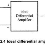
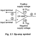
Ideal Operational Amplifier: The Ideal Operational Amplifier is basically an amplifier which amplifies the difference between the two input signals. In its basic form, the Op Amp is nothing but a differential amplifier. To understand the Ideal Characteristics of Operational Amplifier, … (Read More)
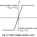
Ideal Voltage Transfer Curve of Op Amp: The ideal op-amp produces the output proportional to the difference between the two input voltages. The graphical representation of this statement gives the voltage transfer curve. … (Read More)
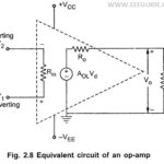
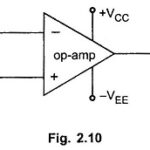
Equivalent Circuit of Practical Op Amp: The Circuit which represents op-amp parameters in terms of physical components, for the analysis purpose is called equivalent circuit of an op-amp. The Equivalent Circuit of Practical Op Amp is shown in the Fig. 2.8. The … (Read More)
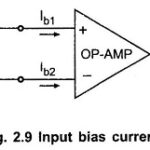
Practical Op Amp Characteristics: The Practical Op Amp Characteristics can be approximated closely enough, for many practical op-amps But basically the Practical Op Amp Characteristics are little bit different than the ideal op-amp characteristics. The various characteristics of a practical op-amp can … (Read More)
Parameters of Operational Amplifier: Two Important Parameters of Operational Amplifier are the slew rate and the power supply rejection ratio (PSRR). Let us discuss and obtain the expressions for these two Parameters of Operational Amplifier Power Supply Rejection Ratio: The power supply rejection … (Read More)
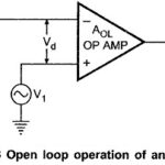
Open Loop Configuration of Op amp: The simplest possible way to use an operational amplifier is in the open loop mode. The Fig. 2.13 shows an Open Loop Configuration of Op amp. We know that the d.c. supply voltages applied to the … (Read More)
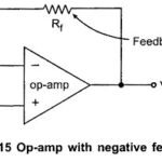
Closed Loop Configuration of Op amp: The utility of op-amp increases considerably if it is used in a closed loop mode. The Closed Loop Configuration of Op amp mode is possible using feedback. The feedback allows to feed some part of … (Read More)
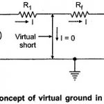
Op Amp Assumptions: We can make two Op Amp Assumptions which are realistic and simplify the analysis of op-amp circuits to a great extent. The Op Amp Assumptions are useful and can be used to obtain the output expressions in variety … (Read More)
Operational Amplifier Applications: The countless simple circuits using one or more operational amplifiers, some external resistors and the capacitors can be constructed. Such Operational Amplifier Applications are classified as Linear applications of op amp Non linear applications of op amp Linear Applications of Op … (Read More)
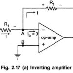
Inverting Amplifier using Op Amp: As the name suggests the output of such an amplifier is inverted as compared to the input signal. The inverted output signal means having a phase shift of 180° as … (Read More)
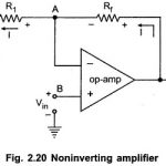
Non Inverting Operational Amplifier: An amplifier which amplifies the input without producing any phase shift between input and output is called Noninverting Amplifier. The basic circuit diagram of a Non Inverting Operational Amplifier is shown in the Fig. 2.20. The input … (Read More)
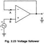
Voltage Follower Op Amp: A circuit in which the output voltage follows the input voltage is called voltage follower circuit. The Voltage Follower Op Amp circuit diagram is shown in the Fig. 2.23. The node B is at potential Vin. Now node A is … (Read More)
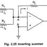
Summing Amplifier: As the input impedance of an op-amp is extremely large, more than one input signal can be applied to the inverting amplifier. Such circuit gives the addition of the applied signals at the output. Hence it is called Summer … (Read More)
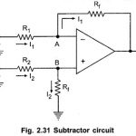
Subtractor using Op Amp or Difference Amplifier Circuit: Similar to the summer circuit, the subtraction of 2 input voltages is possible with the help of op-amp circuit called subtractor or difference amplifier circuit. The Subtractor using Op Amp circuit diagram is … (Read More)
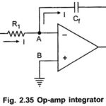
Op Amp Integrator Circuit: In an Op Amp Integrator Circuit, the output voltage is the integration of the input voltage. The integrators circuit can be obtained without using active devices like op-amp, transistors etc. in such a case an integrator is … (Read More)
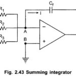
Summing Integrator Circuit: Many useful circuits can be designed using the basic integrator circuit. One of such useful circuits is the Summing Integrators. It can be obtained by applying more than one input to the basic integrator circuit. The Summing Integrator … (Read More)
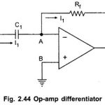
Ideal Active Op Amp Differentiator circuit: The circuit which produces the differentiation of the input voltage at its output is called Differentiator. The differentiator circuit which does not use any active device is called passive Differentiator. While the differentiator using an … (Read More)
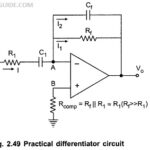
Practical Differentiator: The noise and stability at high frequency can be corrected, in the practical differentiator circuit using the resistance R1 in series with C1 and the capacitor Cf in parallel with resistance Rf. The circuit is shown in the Fig. 2.49. … (Read More)
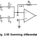
Summing Differentiator Circuit: Similar to the summing integrator, summing can be obtained using the basic differentiator Circuit. It can be obtained by applying more than one input to the basic differentiator Circuit as shown in the Fig. … (Read More)
Instrumentation Amplifier or Data Amplifier: Many industrial systems, consumer systems and process control systems require a precise measurement of the physical quantities like temperature, pressure, humidity, weight etc. A sugar factory requires a measurement of flow, level and … (Read More)
Need of Instrumentation Amplifier: As we know Instrumentation Amplifier are used to amplify the low level differential signals very precisely, in presence of the large common mode noise and interference signals. Hence a good Need of Instrumentation Amplifier has to meet … (Read More)
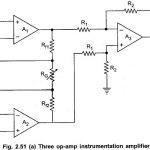
Three Op Amp Instrumentation Amplifier | Block Diagram | Advantages | Applications: The commonly used Instrumentation Amplifier circuit is one using three op amps. This Three Op Amp Instrumentation Amplifier circuit provides high input resistance for accurate measurement of signals from … (Read More)
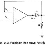
Precision Rectifiers: Recall from basic circuit principles that a rectifier circuits can be implemented with a diode/diodes (half wave rectifier or full wave rectifier). The major limitations of these Precision Rectifiers circuits is that they cannot rectify voltages below VD(ON) = … (Read More)
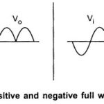
Precision Full Wave Rectifier: The Precision Full Wave Rectifier circuits accept an ac signal at the input, inverts either the negative or the positive half, and delivers both the inverted and noninverted halves at the output, as shown in the Fig. … (Read More)
Op Amp with Diode Circuit: Consider a Op Amp with Diode Circuit as shown in the Fig. 2.68 (a) and the corresponding volt-ampere (V-I) characteristics in the Fig. 2.68 (b). The basic volt-ampere relationship for a diode by using Op amp Circuits … (Read More)
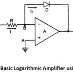
Logarithmic Amplifier using Diode: The circuit diagram of basic Logarithmic Amplifier using Diode is shown in the Fig. 2.69. The diode D is used in the negative feedback path. The node A is grounded hence node B is at virtual ground. Hence … (Read More)
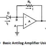
Basic Antilog Amplifier Using Diode: The circuit diagram of basic antilog amplifier using diode is shown in the Fig. 2.70. The positions of diode and resistance are exchanged as compared to log amplifier circuit. The node A is grounded and hence node … (Read More)
What is Active Filters and types of active filters: Active Filters is a circuit that is designed to pass a specified band frequencies while attenuating all the signals outside that band. It is a frequency selective circuit. The filter are basically classified as active filter and … (Read More)
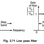
Frequency Response for Low Pass Filter and High Pass Filter: The Fig. 2.71 shows the Frequency Response for Low Pass Filter. A low pass filters has a constant gain from 0 Hz to a high cut-off frequency, fH. Hence, the bandwidth … (Read More)
Filters in Linear Integrated Circuits: The Filters in Linear Integrated Circuits can be represented in the time domain and frequency domain as shown in Fig. 2.73 (a) and (b). As the filter is frequency selective network, the output Vo(t) contains only some of … (Read More)
Butterworth Polynomials: The filter in which denominator polynomial of its transfer function is a Butterworth polynomial is called a Butterworth filters. The Butterworth polynomials of various orders are given in the Tables 2.3 and 2.4. The coefficients of Butterworth polynomials are as given … (Read More)
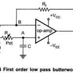
First Order Low Pass Butterworth Filter: The first order low pass butterworth filter is realized by R-C circuit used along with an op-amp, used in the noninverting configuration. The circuit diagram is shown in Fig. 2.74. This also called one pole … (Read More)
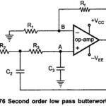
Second Order Low Pass Butterworth Filter: The practical response of Second Order Low Pass Butterworth Filter must be very close to an ideal one. In case of low pass filter, it is always desirable that the gain rolls off very fast … (Read More)
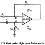
First Order High Pass Butterworth Filter: As mentioned earlier, a high pass filter is a circuit that attenuates all the signals below a specified cut off frequency denoted as fL. Thus, a high pass filter performs the opposite function to that … (Read More)
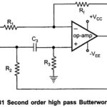
Second Order High Pass Butterworth Filters: The second order high pass Butterworth filters produces a gain roll off at the rate of + 40 dB/decade in the stop band. This filter also can be realized by interchanging the positions of resistors … (Read More)
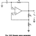
Square Wave Generator Using Op amp: The Square Wave Generator Using Op amp means the astable multivibrator circuit using op-amp, which generates the square wave of required frequency. The Fig. 2.83 shows the square wave generator using op amp. It looks like … (Read More)
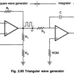
Triangular Wave Generator Using Op amp: We have seen that, the output of integrator is a Triangular Wave Generator Using Op amp if its input is a square wave. This means that a Triangular Wave Generator Using Op amp can be formed … (Read More)
RC Phase Shift Oscillator Using Op amp: RC Phase Shift Oscillator basically consists of an amplifier and a feedback network consisting of resistors and capacitors arranged in ladder fashion. Hence such an oscillator is also called Ladder Type RC Phase Shift … (Read More)
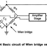
Wien Bridge Oscillator using Op Amp: This is also RC oscillator which uses RC type of feedback network. The main difference between phase shift and Wien bridge oscillator is that the R-C phase shift oscillator introduces 180° phase shift during the … (Read More)
555 Timer Circuit: The timer IC 555 Timer Circuit is most versatile linear integrated device introduced by Signetics corporation in early 1970. It is basically a monolithic timer circuit which can be used in many applications such as monostable and astable … (Read More)
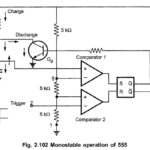
Monostable Multivibrator Using IC 555: The IC 555 timer can be operated as a Monostable Multivibrator Using IC 555 by connecting an external resistor and a capacitor as shown in the Fig. 2.102. The circuit has only one stable state. When trigger … (Read More)
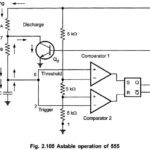
Astable Multivibrator Using IC 555: Fig. 2.105 shows the operation of Astable Multivibrator using 555 Timer IC. The threshold input is connected to the trigger input. Two external resistances RA, RB and a capacitor C is used in the circuit. This circuit … (Read More)
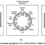
IC 723 Voltage Regulator: The popular general purpose precision regulator is IC 723. It is a monolithic linear integrated circuit in different physical packages. The pin diagram of IC 723 Voltage Regulator along with the various packages is shown in the … (Read More)

Basic Low Voltage Regulator using IC 723: Fig. 2.112 shows the Basic Low Voltage Regulator using IC 723. The resistor, Rsc is connected between CL and CS pins. The current limit transistor remains non-conductive unless drops across Rsc is 0.6 V (equal to … (Read More)
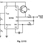
Low Voltage High Current Regulator: Fig. 2.113 shows the Low Voltage High Current Regulator Circuit. Output voltage from +2 to +7 V and load current can be more than 150 mA. For this one transistor is connected externally, shown as Q1 in the … (Read More)
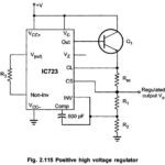
Basic Positive High Voltage Regulator: The Basic Positive High Voltage Regulator is shown in Fig. 2.114 For this type, output voltage varies from +7V to +37V and IL ≤ 150 mA. The non-inverting terminal connected to Vref through R3 . Due to this arrangement … (Read More)
Positive High Voltage High Current Regulator: For this type, output voltage from +7V to +37V and load current IL > 150 mA. For this a external transistor Q1 is connected, as shown in the Fig. … (Read More)
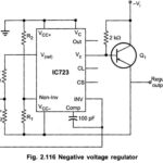
Negative Voltage Regulator: Connections for getting negative voltage regulator are shown in Fig. 2.116. An external PNP transistor, Q1 is connected. Resistances can be from 1 kΩ to 10 kΩ. If magnitude of -Vi is less than 9V, connect VCC+ and VC to a … (Read More)
Protection Circuits in Regulators: The series regulator using transistors has no short circuit protection. If the load terminals are shorted accidentally then, Large amount of load current will flow. The pass transistor Q1 will get destroyed. The diodes used in … (Read More)
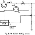
Constant Current Limiting Circuit: A block of series regulation using simple Constant Current Limiting Circuit is shown in the Fig. 2.119. It is also called short circuit protection circuit as it provides protection against short circuiting. The resistance R4 is added … (Read More)
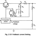
Foldback Current Limiting Circuit: The disadvantage of constant current limit is relatively large power dissipation in the series pass transistor when the load terminals are shorted. Thus a large power rating transistor is required. The Foldback Current Limiting technique allows us … (Read More)
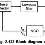
Phase Locked Loop Working Principle: A Phase Locked Loop Working is basically a closed loop system designed to lock the output frequency and phase to the frequency and phase of an input signal. It is commonly abbreviated as Basics of PLL. The … (Read More)
Important Definition of Phase Locked Loop (PLL): Some Important Definition of Phase Locked Loop PLL are as follows : Lock Range: When PLL is in lock, it can track frequency changes in the incoming signal. The range of frequencies over which the PLL … (Read More)
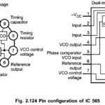
IC 565 PLL | Pin Diagram | Block Diagram: IC 565 PLL is available in a 14 pin DIP package and 10 pin metal can package. Fig. 2.124 shows 14-pin package configuration for IC 565 and Fig. 2.125 shows the block … (Read More)
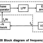
Frequency Multiplier using PLL 565: Fig. 2.128 shows the block diagram for a frequency multiplier using PLL 565. Here , a divide by N network is inserted between the VCO output (pin 4) and the phase comparator input (pin 5). Since the … (Read More)
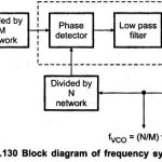
Block Diagram of Frequency Synthesizer using PLL: The Block Diagram of Frequency Synthesizer using PLL that can produce a precise series of frequencies that are derived from a stable crystal controlled oscillator. The Fig. 2.130 shows the Frequency Synthesizer Block Diagram. It … (Read More)
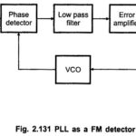
PLL FM Detector or Demodulator: The PLL can be very easily used as an FM detector or demodulator. Fig. 2.131 shows the PLL FM Detector or Demodulator Block Diagram. When the PLL is locked in on the FM signal, the VCO frequency … (Read More)
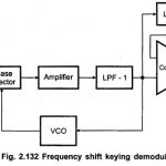
Frequency Shift Keying Demodulator Working (FSK): In digital data communication, binary data is transmitted by means of a carrier frequency. It uses two different carrier frequencies for logic 1 and logic 0 states of binary data signal. This type of data … (Read More)
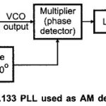
AM Detection using PLL: AM Detection – A PLL can be used to demodulate AM signals as shown in the Fig. 2.133. The PLL is locked to the carrier frequency of the incoming AM signal. Once locked the output frequency of VCO … (Read More)
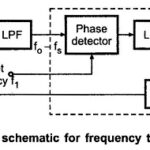
Frequency Translator using PLL: The Frequency Translator means shifting the frequency of an oscillator by a small factor. Fig. 2.134 shows the block schematic for frequency translator using PLL. It consists of mixer, low pass filter and the PLL. The input frequency … (Read More)