Linear Wave Shaping Articles:
High Pass RC Circuit Diagram, Derivation and Application: The High Pass RC Circuit is shown in Fig. 29.1. The reactance of the capacitor is given as i.e., Reactance XC of the circuit capacitor decreases with the increase in frequency. Thus at low … (Read More)
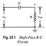
RC High Pass Circuit as Differentiator: RC High Pass Circuit as Differentiator – A circuit that gives an output voltage proportional to the derivative of its input, is known as a Differentiator circuit. Figure 29.1 shows a typical RC High Pass Circuit as … (Read More)
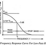
Low Pass RC Circuit Diagram, Derivation and Application: The Low Pass RC Circuit is shown in Fig. 29.18. In a Low Pass RC Circuit, the output voltage vout is taken across the capacitor. Resistance offers fixed opposition. Since the reactance offered … (Read More)
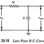
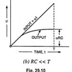
RC Integrator Circuit Diagram and its Application: A circuit that gives an output voltage directly proportional to the integral of its input is known as integrating circuit. Figure 29.18 shows a typical RC Integrator Circuit diagram. The output voltage across capacitor C … (Read More)
Double Differentiation – Derivation: Two R-C coupling networks in cascade separated by an amplifier A is shown in Fig. 29.36 (a). The amplifier A is to operate as a linear amplifier and the output impedance must be small with respect to … (Read More)