Load Equalisation in Electrical Drives:
Load Equalisation in Electrical Drives – In some drive applications, load torque fluctuates widely within short intervals of time. For example, in pressing machines a large torque of short duration is required during pressing operation, otherwise the torque is nearly zero. Other examples are electric hammer, steel rolling mills and reciprocating pumps. In such drives, if motor is required to supply peak torque demanded by load, first motor rating has to be high. Secondly, motor will draw a pulsed current from the supply. When amplitude of pulsed current forms an appreciable proportion of supply line capacity, it gives rise to line voltage fluctuations, which adversely affect other loads connected to the line. In some applications, peak load demanded may form major proportion of the source capacity itself, as in blooming mills, then load fluctuations may also adversely affect the stability of source.
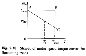
Above mentioned problems of fluctuating loads are overcome by mounting a flywheel on the motor shaft in non-reversible drives. Motor speed-torque characteristic is made drooping. Alternatively, by closed loop current control torque is prevented from exceeding a permissible value. During high load period, load torque will be much larger compared to the motor torque. Deceleration occurs producing a large dynamic torque component (J dωm/dt). Dynamic torque and motor torque together are able to produce torque required by the load (Eq. (2.2)). Because of Fig. 2.10 Shapes of motor speed torque curves for deceleration, the motor speed falls. During light load period, the motor torque exceeds the load torque causing acceleration Speed is brought back to original value before the next high load period.
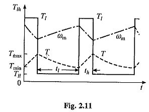
Variation of motor and load torques, and speed for a periodic load and for a drooping motor speed-torque curve are shown in Fig. 2.11. It shows that peack torque required from the motor has much smaller value than the peak load torque. Hence, a motor with much smaller rating than peak load can be used and peak current drawn by motor from the source is reduced by a large amount. Fluctuations in motor torque and speed are also reduced. Since power drawn from the source fluctuates very little, this is called load equalisation.
In variable speed and reversible drives, a flywheel cannot be mounted on the motor shaft, as it will increase transient time of the drive by a large amount. If motor is fed from a motor-generator set (Ward-Leonard Drive), then flywheel can be mounted on the shaft of the motor-generator set. This arrangement of Load Equalisation in Electrical Drives on the source, but not the load on motor. Consequently, a motor capable of supplying peak-load-torque is required.
Moment of inertia of the flywheel required for Load Equalisation in Electrical Drives is calculated as follows: Assuming a linear motor-speed-torque curve in the region of interest
where ωm0,ωmr and and Tr are no-load speed, rated speed and rated torque, respectively.
Because of slow response due to large inertia, motor can be assumed to be in electrical equilibrium during transient operation of the motor-load system. In that case Eq. (2.31) will be applicable for the transient operation also. Differentiating (2.31) and multiplying both sides by J gives
where
Term τm is defined as the mechanical time constant of the motor. It is the time required for the motor speed to change by (ωm0 – ωmr) when motor torque is maintained constant at rated value Tr.
From Eqs. (2.2) and (2.33)
Consider now a periodic load torque, a cycle of which consists of one high load period with torque Tlh and duration th, and one light load period with torque Tll and duration tt (Fig. 2.11). For high load period (0 ≤ t ≤ th) solution of Eq. (2.35) is
where Tmin is the motor torque at t= 0, which is also the instant when heavy load Tlh is applied. If motor torque at the end of heavy load period is Tmax, then from Eq. (2.36)
Solution of Eq. (2.35) for the light load period (th ≤ t ≤ th + tl) with the initial motor torque equal to Tmax is
When operating in steady-state, motor torque at the end of a cycle will be the same as at the beginning of cycle. Hence at t′ = tl, T = Tmin. Substituting in Eq. (2.38) gives
From Eq. (2.37)
From (2.34) and (2.41)
Also from Eq.(2.40)
From Eqs. (2.34) and (2.43)
 Moment of inertia of the flywheel required can be calculated either from Eq. (2.42) or (2.44). Further
where W is the weight of the flywheel (kg) and R is the radius (m).


