Low Frequency Response of FET Amplifier:
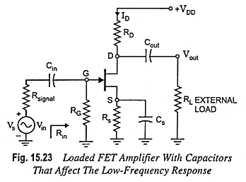
The analysis of the Low Frequency Response of FET Amplifier is quite similar to that of the BJT amplifier. Though here common-source configuration is considered but the results can be applied to most FET configurations. For the circuit given in Fig. 15.23, the capacitors Cin, Cout and CS will determine low frequency response. Now we will examine the impact of each independently.
Effect of Cin on Frequency Response of FET Amplifier:
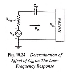
For the coupling capacitor Cin connected between the applied source and the active device, the general form of the R-C combination is established by the network shown in Fig. 15.24.
The cutoff frequency is given by the equation
For network given in Fig. 15.23
Typically RG ≫ Rsignal and lower cutoff frequency is determined primarily by RG and Cin. The fact that RG is so large permits a relatively low level of Cin while maintaining a low frequency level for fLi.
Effect of Cout on Frequency Response of FET Amplifier:
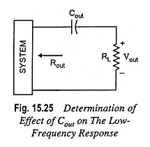
The output capacitor Cout is normally connected between the output of the active device and the load, therefore, the R-C configuration determining the lower cut-off frequency due to Cout will appear as shown in Fig. 15.25.
From Fig. 15.25, the total series resistance is Rout + RL and the cutoff frequency due to Cout is given by the equation
The value of Rout for the circuit given in Fig. 15.23 is given by equation
Determination of Effect of Cs on The Low-Frequency Response:
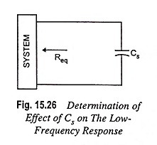
For determination of frequency fLs, the network “seen” by Cs must be determined as illustrated in Fig. 15.26.
Once the level of Req is determined the cutoff frequency due to Cs may be computed from the equation
For Fig. 15.23, the resulting value of Req is given by the equation
which for rd ≡ α Ω becomes


