Magnetic Tape Recorder Working Principle:
The major advantage of using a Magnetic Tape Recorder Working Principle is that once the data is recorded, it can be replayed an almost indefinite number of times.
The recording period may vary from a few minutes to several days. Speed translation of the data captured can be provided, i.e. fast data can be slowed down and slow data speeded up by using different record and reproduce speeds.
The recorders described earlier have a poor high frequency response. Magnetic tape recorder, on the other hand, have a good response to high frequency, i.e. they can be used to record high frequency signals. Hence, magnetic tape recorders are widely used in instrumentation systems.
Basic Components of Magnetic Tape Recorder:
A magnetic tape recorder consists of the following basic components.
- Recording Head
- Magnetic Head
- Reproducing Head
- Tape transport mechanism
- Conditioning devices
Magnetic Recording:
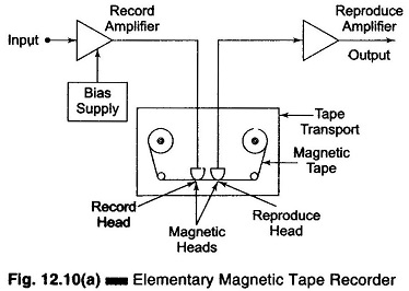
The basic elements of a simple Magnetic Tape Recorder Working Principle system are illustrated in Fig. 12.10(a).
The Magnetic Tape Recorder Working Principle is made of a thin sheet of tough, dimensionally stable plastic, one side of which is coated with a magnetic material.
Some form of finely powdered iron oxide is usually cemented on the plastic tape with a suitable binder. As the tape is transferred from one reel, it passes across a magnetising head that impresses a residual magnetic pattern upon it in response to an amplified input signal.
The methods employed in recording data on to the magnetic tape include direct recording, frequency modulation (FM) and pulse code modulation (PCM).
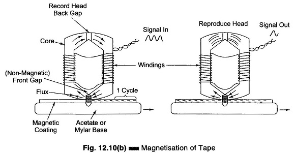
Modulation of the current in the recording head by the signal to be recorded linearly modulates the magnetic flux in the recording gap. As the tape moves under the recording head, the magnetic particles retain a state of permanent magnetization proportional to the flux in the gap. The input signal is thus converted to a spatial variation of the magnetization of the particles on the tape. The reproduce head detects these changes as changes in the reluctance of its magnetic circuit which induce a voltage in its winding. This voltage is proportional to the rate of change of flux. The reproduce head amplifier integrates the signal to provide a flat frequency characteristics.
Since the reproduce head generates a signal which is proportional to the rate of change of flux, the direct recording method cannot be used down to dc. The lower limit is around 100 Hz and the upper limit for direct recording, around 2 MHz. The upper frequency limit occurs when the induced variation in magnetization varies over a distance smaller than the gap in the reproduce head.
The signal on an exposed tape can be retrieved and played out at any time by pulling the tape across the magnetic head, in which a voltage is induced.
It is possible to magnetize the tape longitudinally or along either of the other two main axis, but longitudinal magnetization is the best choice.
Figure 12.10(b) shows simply how the tape is magnetized. If a magnetic field is applied to any one of the iron oxide particles in a tape and removed, a residual flux remains. The relationship between the residual flux and the recording field is determined by the previous state of magnetization and by the magnetization curves of the particular magnetic recording medium.
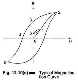
A simple magnetic particle on the tape might have the B – H curve shown in Fig. 12.10(c) where H is the magnetizing force and B the flux density in the particle.
Consider the material with no flux at all, i.e. the condition at point 0. Now if the current in the coil of the recording head [Fig. 12.10(b)] is increased from 0 in a direction that gives positive values of H, the flux density increases along the path 0 – 1 – 2, until the material is eventually saturated. If the operating point is brought from 0 only as far as 1, and H is brought back to 0, B follows a minor hysteresis loop back to point 6. A greater value of coil current would leave a higher residual flux, and a lower current a lower residual; a very simple recording process results.
However, the linearity between residual flux and recording current is very poor. Hence to obtain linearity in direct recording, FM is used. In all systems, the signal is reproduced by passing the magnetized tape over a magnetic head similar to the recording head. The magnetization of the particles on the tape induces a varying flux in the reproducing head and a voltage is induced in the coil, proportional to the rate of change of flux.
Methods of Magnetic Tape Recording:
There are three methods of magnetic tape recording which are used for instrumentation purposes.
- Direct recording
- FM recording
- Pulse Duration Modulation recording (PDM)
FM recorders are generally used for instrumentation purposes. PDM recording is used in instrumentation for special applications where a large number of slowly changing variables have to be recorded simultaneously.


