BH Curve Relationship (Magnetization Characteristic) for Ferromagnetic Material:
In free space (also nonmagnetic materials), the permeability μ0 is constant so that BH Curve Relationship is linear. This, however, is not the case with ferromagnetic materials used in electric machines, wherein the BH Curve Relationship of Ferromagnetic Material is strictly nonlinear in two respects saturation and hysteresis.
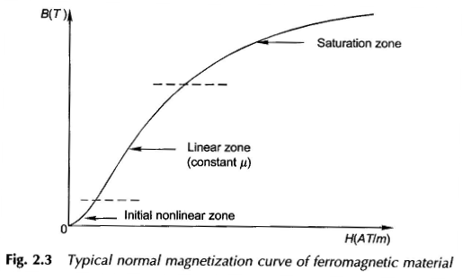
Hysteresis non-linearity is the double valued B-H relationship exhibited in cyclic variation of H (i.e. exciting current). This nonlinearity is usually ignored in magnetic circuit calculations and is important only when current wave shape and power loss are to be accounted for. A typical normal BH Curve Relationship of Magnetization Characteristic for ferromagnetic material is shown in Fig. 2.3. It has an initial nonlinear zone, a middle almost linear zone and a final saturation zone in which B progressively increases less rapidly with H compared to the linear zone. In the deep saturation zone, the material behaves like free space.
Due to considerations dictated by economy, electric machines and transformers are designed such that the magnetic material is slightly saturated (i.e somewhat above the linear zone). In exact magnetic circuit calculations the nonlinear magnetization curve has to be used necessitating graphical/numerical solutions.
Core with Air-gap:
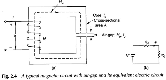
Transformers are wound on closed cores as in Fig. 2.1. Rotating machines have a moving element and must therefore have air-gaps in the cores out of necessity. A typical magnetic circuit with an air-gap is shown in Fig. 2.4. It is assumed that the air-gap is narrow and the flux coming out of the core passes straight down the air-gap such that the flux density in the air-gap is the same as in the core. Actually as will soon be seen, the flux in the gap fringes out so that the gap flux density is somewhat less than that of the core. Further, let the core permeability μc be regarded as constant (linear magnetization characteristic).
The mmf Ni is now consumed in the core plus the air-gap. From the circuit model of Fig. 2.4(b) or directly from Fig. 2.4(a)
Assuming that all the core flux passes straight down the air-gap (it means no fringing (see Fig. 2.5))
Substituting Eq. (2.10) in Eq. (2.9b)
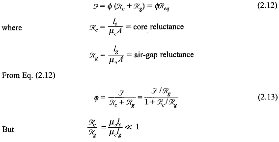
Recognizing various quantities in Eq. (2.11)
because μc is 2000 to 6000 times μ0 in ferromagnetic material. The permeability effect predominates the usual core and air-gap dimensions even though lc≫ Ig. It then follows from Eq. (2.13), that![]()
which means that in a magnetic circuit with air-gap(s), core reluctance may be neglected with no significant loss of accuracy. This assumption will be generally made in modelling rotating machines. The effect of core saturation (reduction of core permeability) will be introduced as a correction wherever greater accuracy is desired.


