Magnetization Characteristics of DC Generator:
The emf and torque equations, and power balance has been considered so far. The consideration of the Magnetization Characteristics in this section will set the stage for determining the performance of dc machines.
Figure 2.3 depicted the magnetization curve of ferromagnetic material (iron) which is the B-H relationship. In a machine instead of this relationship which holds at any point in the magnetic field, it is more useful to define the magnetization relationship in terms of gross quantities, i.e. the air-gap flux/pole, Φ, and the excitation mmf measured as field current, If. There is no convenient way of directly measuring Φ in a machine. Relation (7.4) is, therefore, made use of, wherein
from which it is obvious that the machine emf Ea is a measure of Φ so long as the armature is run at constant speed. The Magnetization Characteristics of the dc machine is then determined by measuring the armature open-circuit (la= 0) voltage,
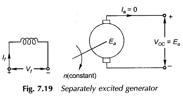
at rated armature speed, while gradually raising If from zero onwards till a value of VOC well above that of the rated voltage of the machine (usually about 125%) is reached. In determining this characteristic the machine must be separately excited as a generator and run at rated speed by external means (prime-mover) as shown in Fig. 7.19.
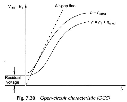
A typical Magnetization Characteristics is shown in Fig. 7.20. It is known as open-circuit characteristic (OCC) because of the method by which it is determined. It exhibits all the important characteristics of the magnetization curve of iron, modified by the presence of an air-gap in the magnetic circuit.
In conducting the OCC test, If must be raised gradually only in the forward direction otherwise the curve would exhibit local hysteresis loops. Further, as the machine would have been previously subjected to magnetization, a small residual voltage would be present with field unexcited. As will be seen presently, this is necessary for generator self-excitation.
The extension of the linear portion of the magnetization curve, shown dotted in Fig. 7.20, is known as the air-gap line as it represents mainly the magnetic behaviour of the machine’s air-gap, the iron being unsaturated in this region consumes negligible ampere-turns; in any case the effect of iron is also linear here.
The open-circuit characteristic at a speed other than the one at which the test is conducted is a mere proportional translation of the characteristic as shown in Fig. 7.20. This is because of the direct proportionality between Ea and n.
As a matter of convenience, the OCC test is generally conducted by exciting the main field winding as has been assumed above. However, in a compound machine where both shunt and series windings are excited, the value of induced emf can be read from the OCC against the equivalent main field current
where
- Nf = main field turns
- Nse = series field turns
- If = main field current
- Ise = series field current
- ± sign is decided by cumulative/differential compounding
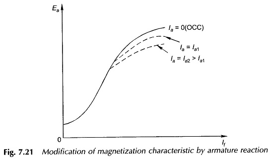
It was seen from earlier section that the flux/pole and therefore the induced emf is reduced by the demagnetizing effect of the armature reaction in the saturation region of the magnetization curve. The induced emf is now expressed as the more general functional relationship Ea(If, Ia) whose three plots la = 0(OCC), Ia = Ia1 and Ia =Ia2 > Ia1 are shown in Fig. 7.21. Other than the actual loading test (as generator), there is no easy way to measure the reduction in induced emf caused by the armature current. Generally certain empirical relationships are employed for this correction. One empirical method to account for demagnetizing effect of armature reaction in presence of saturation is to include equivalent demagnetizing ampere-turns ATd in calculation of the net ampere-turns acting on each pole, i.e.,
where
- ATf = main field ampere-turns
- ATse = series field ampere-turns (Cumulative/differential)
- ATd can be taken proportional to Ia with an appropriately determined proportionality constant.


