Frequency Measurement by Lissajous Method:
The oscilloscope is a sensitive indicator for frequency and phase measurements. This Frequency Measurement by Lissajous Method techniques used are simple and dependable, and measurement may be made at any frequency in the response range of the oscilloscope.
One of the quickest methods of determining frequency is by using Lissajous patterns produced on a screen. This particular pattern results when sine waves are applied simultaneously to both pairs of the deflection plates. If one frequency is an integral multiple (harmonic) of the other, the pattern will be stationary, and is called a Lissajous figure.
In this Frequency Measurement by Lissajous Method a standard frequency is applied to one set of deflection plates of the CRT tube while the unknown frequency (of approximately the same amplitude) is simultaneously applied to the other set of plates. However, the unknown frequency is presented to the vertical plates and the known frequency (standard) to the horizontal plates. The resulting patterns depend on the integral and phase relationship between the two frequencies. (The horizontal signal is designated as fh and the vertical signal as fv).
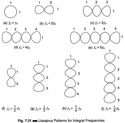
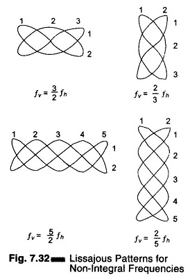
Typical Lissajous figures are shown in Figs 7.31 and 7.32 for sinusoidal frequencies which are equal, integral and in ratio.
Measurement Procedure:
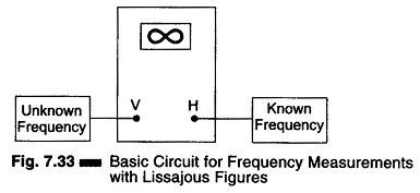
Set up the oscilloscope and switch off the internal sweep (change to Ext). Switch off sync control. Connect the signal source as given in Fig. 7.33. Set the horizontal and vertical gain control for the desired width and height of the pattern. Keep frequency fv constant and vary frequency fh, noting that the pattern spins in alternate directions and changes shape. The pattern stands still whenever fv and fh are in an integral ratio (either even or odd). The fv = fh pattern stands still and is a single circle or ellipse. When fv = 2 fh, a two loop horizontal pattern is obtained as shown in Fig. 7.31.
To determine the frequency from any Lissajous figure, count the number of horizontal loops in the pattern, divide it by the number of vertical loops and multiply this quantity by fh (known or standard frequency).
In Fig. 7.31 (g), there is one horizontal loop and 3 vertical loops, giving a fraction of 1/3. The unknown frequency fv is therefore 1/3 fh. An accurately calibrated, variable frequency oscillator will supply the horizontal search frequency for Frequency Measurement. For the case where the two frequencies are equal and in phase, the pattern appears as a straight line at an angle of 45° with the horizontal. As the phase between the two alternating signals changes, the pattern changes cyclically, i.e. an ellipse (at 45° with the horizontal) when the phase difference is π/4, a circle when the phase difference is π/2 and an ellipse (at 135° with horizontal) when the phase difference is 3π/4, and a straight line pattern (at 135° with the horizontal) when the phase difference is π radians.
As the phase angle between the two signals changes from π to 2π radians, the pattern changes correspondingly through the ellipse-circle-ellipse cycle to a straight line. Hence the two frequencies, as well as the phase displacement can be compared using Lissajous figures techniques.
When the two frequencies being compared are not equal, but are fractionally related, a more complex stationary pattern results, whose form is dependent on the frequency ratio and the relative phase between the two signals, as in Fig. 7.32.
The fractional relationship between the two frequencies is determined by counting the number of cycles in the vertical and horizontal.
Figure 7.33 illustrates the basic circuit for comparing two frequencies by the Lissajous method.


