Methods of Controlling Chopper Circuit:
The basic principle of control of a Chopper Circuit is the effective change of the value of the time ratio. This is done in two ways:
1.Time ratio control
2.Current limit control
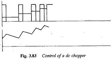
In the former, the ratio TON/T is varied. This can be achieved by varying TON, keeping the chopper period T constant, which is called pulse width control or constant frequency control. The waveforms of voltage and current for this type of control are shown in Fig. 3.83. The variation of the time ratio can also be achieved by keeping TON constant and varying the chopper period T, which is called pulse frequency control or variable frequency control. The waveforms of voltage and current for this method are depicted in Fig. 3.83. From the waveforms it is clear that the maximum and minimum values of load current are decided by the ratio of TON/T. The variable frequency control is more prone to discontinuous conduction than constant frequency control.
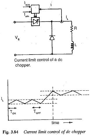
In current limit control (Fig. 3.84), the load current is allowed to vary between two given (upper and lower) limits. The ON and OFF times of the Chopper Circuit adjust automatically. When the current increases beyond the upper limit the chopper is turned off. The load current free wheels and starts to decrease. When it falls below the lower limit the Chopper Circuit is turned ON. The current starts increasing in the load. The load current and voltage waveforms are shown in Fig. 3.84. The amplitude of the ripple can be controlled in this case by assuming proper limits of current. The lower the ripple current, the higher the chopper frequency. By this switching losses increase. Discontinuous conduction can also be avoided in this case, which makes this method superior to time ratio control in this regard.

