Methods of Discrimination in Power System Protection:
Methods of Discrimination in Power System Protection are basically of two types:
- those which discriminate as to the location of fault, and
- those which discriminate as to the type of fault.
Methods Discriminative to Fault Location:
The main aim is that the faulty section of the system be isolated and in the minimum time. The various methods under this category are those in which the behavior of the protective apparatus is dependent upon where it is situated in the system relative to the point of fault occurrence.
(a) Discrimination by Time: By adding time lag features to the controlling relays of a number of circuit breakers it is possible to trip the breaker nearest the fault prior to those farther off the point of fault. This simple scheme may be applied in a radial feeder shown in Fig. (2.1).
The breakers at A, B, C and .D are identical and are set to operate for a given value of current. For a fault in any section, say CD, if the fault current exceeds the set value the breakers at A, B and C will trip and the whole feeder beyond A becomes dead.
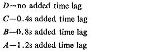
For providing time lag to the circuit breakers at A, B, C, and D the tripping is delayed in the following manner:
With such a scheme obviously if the fault occurs in the section CD the breaker at C will trip after a time of 0.4s and thus wilt clear the fault with the result that the feeder up to C will remain alive. A 0.4s step time lag is necessary to account for the time of operation of circuit breaker and its relay operation times.
(b) Discrimination by Current Magnitude: This depends on the current magnitudes as the magnitude of the fault current will also vary with the location of the fault. If the relays are set to pickup at a progressively higher current towards the source then a simple feeder system pf the type shown in Fig. (2.1) can be protected. Such a scheme is known as current graded scheme.
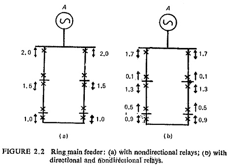
(c) Discrimination by Time and Direction: In the case of a ring main which forms a closed loop it is not possible to isolate the faulty section with the help of time alone. Consider the ring main shown in Fig. (2.2). In one case non-directional relays with same current setting but different time lags are provided which shows that proper discrimination cannot be obtained nor can this position be improved by varying the time lags from those shown in the diagram.
In the second case for the same ring main directional feature is also introduced as shown by arrows. Now it can be seen that a fault occurring on any section will be discriminatively cleared without loss of supply.
(d) Discrimination by Distance Measurement: The methods described above which discriminate by time and current magnitude have limitations of being applicable to simple systems. Moreover the faults nearer to the source which are more severe take longer time to clear in the case of time Methods of Discrimination in Power System Protection.
Now if the relays are designed to measure the distance from the breaker location to the fault and if this distance happens to be less than that to the next breaker out from the source, the fault is within the section controlled by the breaker concerned and this trips. if the distance is greater-than that to the next breaker out from the source, the fault is beyond the section controlled by the breaker concerned and therefore it does not trip. All successive breakers are controlled in this way and are set to operate only for faults in their own section.
The measurement of distance is achieved in various ways by what are known as distance relays to be discussed later.
(e) Time as an Addition to Current Magnitude or Distance Discrimination: Combination of time with current magnitude discrimination or with distance discrimination gives practical dimension to protection. It will be seen later that combination of time and current grading gives the most practical protection schemes and similarly the time distance discrimination forms another practical protection scheme.
(f) Current-Balance Discrimination: The discriminative methods outlined above may not be adequate for a complex system having interconnections and alternative parallel’paths, etc. This calls for a form of discrimination which is limited in its scope to one system element which will cause isolation of this element only in the event of fault in this element and will not respond to any other fault external to this element, even though the fault current passes through it Such a protection is known as unit protection.
This form of protection is based on one of the following two principles: (a) circulating current principle; (b) opposed voltage principle or balanced voltage principle.
The circulating current principle compares the currents at the two ends of the protected section. This is illustrated in Fig. (2.3a), the difference of the current magnitude at the two ends flows through the relay. For an external fault the balance of currents is not disturbed and the section or apparatus is not isolated, whereas for a fault within the apparatus or the protected section the balance of currents is disturbed and the relay trips the breakers at the two ends and isolates this section completely.
The principle of balanced-voltage protection is shown in Fig. (2.3b). Here the relative polarity of the CTs at the two ends is such that there is no pilot current for the conditions of load or external fault. The CT secondary voltages will no longer balance and current will flow in the relays which will trip the circuit breakers at the two ends.
(g) Power-Direction Comparison Discrimination: In this case the comparison of the direction of fault power at the two ends of the protected section is done by directional relays. Under external fault conditions the direction of the fault power is outwards at one end of the protected section. Under internal fault conditions, fault power is fed only into the section either at both ends or at one end, depending upon whether the source of power supply is on both sides or only on one side of the protected section. Figure (2.4) illustrates the principle of power directional comparison.
Considering one end of the line only and assuming that power flows into the line at this end, one of the following three things simultaneously applies:
- Power flows out at the other end, which means either load conditions or external fault conditions obtained ;so tripping should be prevented.
- Power also flows in at the other end, which means an internal fault condition and both breakers should trip.
- No power flows either in or out at the other end, meaning thereby that there is no source on the other end and thus if the power flow is of sufficient magnitude it is due to fault in the section and the local breaker on this side only should trip.
The scheme outlined needs considerable elaboration to give it a practical shape.
(h) Phase Comparison Discrimination: This is another form of power line carrier protection. In this case the phase angle of current at the two ends of the protected section is compared, which gives an indication whether the fault is internal or external. Information about the phase angle of the primary current is transmitted to the other end over the carrier link.
Methods Discriminative to Type of Fault:
There can be cases when the fault currents may not be very high or may differ little in magnitude from load currents with the result that current magnitude detection fails to point out such a fault. Such a fault current however has some peculiarity which distinguishes itself from the normal load currents. For instance, in a three phase system the currents and voltages can be resolved into their phase sequence components which would ultimately give some idea about the nature of the currents or voltages present.
(a) Zero-Phase Sequence Networks: These networks are commonly used for the detection of earth faults. By providing a relay at such a place where it will be energized only by zero-sequence currents an indication is obtained of an earth fault as shown in Fig. (2.5). Such a relay will ignore load currents or phase-to-phase short circuits. Hence the setting of such a relay will have no bearing on the load current values which is often essential for Methods of Discrimination in Power System Protection or even for adequate protection when earth currents are limited.
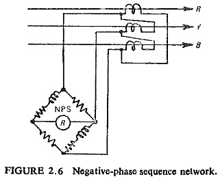
(b) Negative-Phase Sequence Networks: The presence of negative-phase
sequence current represents some form of unbalanced condition such as phase-to-phase faults other than the symmetrical three-phase faults, broken conductors, etc. A typical negative phase sequence network is shown in Fig. (2.6).
Discrimination by Combinations of Methods Sensitive to Location and Type of Fault:
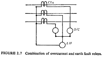
A combination of the methods discriminative to fault location and the methods discriminative to type of fault is very useful in actual practice. An .example of such a combination is a protective scheme providing protection by overcurrent and earth fault relays. This uses time current discrimination and zero sequence device. Such a scheme is shown in Fig. (2.7).


