Methods of Excitation of DC Generator:
The performance characteristics of a dc machine are greatly influenced by the way in which the field winding is excited with direct current. There are two Methods of Excitation of DC Generator.
- Shunt excitation: Here the field winding is provided with a large number of turns of thin wire and is excited from a voltage source. The field winding, therefore, has a high resistance and carries a small current. It is usually excited in parallel with armature circuit and hence the name shunt field winding. Since the armature voltage of a dc machine remains substantially constant, the shunt field could be regulated by placing an external series resistance in its circuit.
- Series excitation: Here the field winding has a few turns of thick wire and is excited from armature current by placing it in series with armature, and therefore it is known as series field winding. For a given field current, control of this field is achieved by means of a diverter, a low resistance connected in parallel to series winding. A more practical way of a series field control is changing the number of turns of the winding by suitable tappings which are brought out for control purpose.
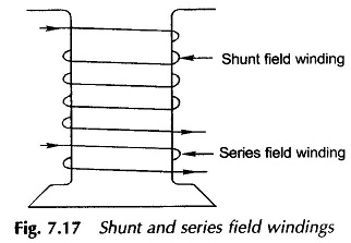
Figure 7.17 shows the physical arrangement of shunt and series field windings on one pole of a machine.
Excellent and versatile ways of controlling the shunt and series excitations are now possible by use of solid-state devices and associated control circuitry.
Another way of classifying Methods of Excitation of DC Generator, which is meaningful for dc machines used as a generator, is to distinguish whether the machine field is excited by its own armature voltage/current or an independent source is used for this purpose.
The two distinct classes of Methods of Excitation of DC Generator from this point of view are:
- Separate excitation
- Self excitation
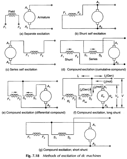
In separate excitation a separate dc source is needed for excitation purposes only and is obviously inconvenient. The separate excitation arrangement, the shunt field winding, is shown in Fig. 7.18(a). The separately excited machine is most flexible as full and independent control of both armature and field circuits is possible. Permanent magnet machines also fall into this category.
A self-excited dc generator could be excited by its own armature voltage (shunt excitation) as in Fig. 7.18(b) or by its own current (series excitation) as in Fig. 7.18(c). A combination of shunt and series excitation (compound excitation) is also used for generators as discussed later in this section. A self-excited generator may fail to excite under certain field conditions.
A dc machine when used as a motor has its shunt field always separately excited as its excitation is drawn from the dc supply. Figures 7.18(b) and (c) are valid shunt and series excitation schemes for dc motors.
If both shunt and series excitations are used in a dc machine as in Fig. 7.18(d), it is called a compound dc machine. If the series field flux aids the shunt field flux, so that the resultant air-gap flux per pole is increased, then the machine is called a cumulatively compounded dc machine (Fig. 7.18(d)). However, if a series field flux opposes the shunt field flux, so that the resultant air-gap flux per pole is decreased, the machine is called a differentially compounded dc machine (Fig. 7.18(e)). In Fig. 7.18, the field and armature circuits are drawn at 90° (elect.) with respect to each other which represents, as pointed out earlier, the actual spatial orientation of the magnetic fields produced by field and armature circuits in a dc machine.
The direction of the arrows in Figs 7.18(d) and (e) corresponds to the magnetic fields associated with the two field windings. Figure 7.18(d) implies that the magnetic fields of two field windings are additive. Cumulative compounding of both motors and generators are often used to exploit the merits of both shunt and series excitations.
Of course, now with the advent of solid-state control for both armature and field circuits, this method has lost much of its charm. The differential compound machine has hardly any practical applications. In fact differentially compounded motor can become unstable (acquires dangerously high speeds) in a certain region of operation (at even moderate overloads).
From the viewpoint of connections, a dc compound machine may have short-shunt (Fig. 7.18(g)) or a long-shunt (Fig. 7.18(f)) connection. These are two possible ways of connecting the shunt field winding in a compound machine. But there is no appreciable difference in their machine performance characteristics. The choice between them depends on mechanical considerations or reversing switches.
Steady-state Circuit Equations:
In steady-state operation of a dc machine, armature and field inductances do not play any role in steady-state circuit equations of the machine. With reference to Fig. 7.18(f) of a long-shunt compound machine applying the Kirchhoff s voltage and current laws, the following steady-state circuit equations of the machine can immediately be written:
where the plus sign is used for motoring operation and minus for generating operation.

