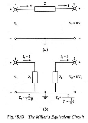
Millers Theorem and its Equivalent Circuit:
Millers theorem – Consider an arbitrary circuit shown in Fig. 15.13(a). As part of a larger network that is not shown, we have isolated two circuit nodes, labelled 1 and 2, between which an impedance Z is connected. Nodes 1 and 2 are also connected to other parts of the network, as signified by the broken lines emanating from two nodes. Furthermore, it is assumed that somehow it has been determined that the voltage at node 2 is related to the voltage at node 1 by equation
In typical situations K is a gain factor that may be positive or negative and that has a magnitude usually greater than unity (i.e., K > 1). This, however, is not an assumption for Millers theorem.
According to Millers theorem, impedance Z can be replaced by two impedances : Z1 connected between node 1 and ground and Z2 connected between node 2 and ground, where
to obtain the equivalent circuit illustrated in Fig. 15.13(b).
Millers theorem can be proved by deriving Eq. (15.36) as follows :
In the circuit shown in Fig. 15.13(a), the only way that node 1 “feels the existence” of impedance Z is through the current I that Z draws away from node 1. Therefore, in order to keep this current I unchanged in the equivalent circuit, the value of Z1 must be selected so that it may draw an equal current
Similarly to keep the current into node 2 unchanged we must choose the value of Z2 so that
The Millers equivalent circuit derived above is valid only as long as the rest of the circuit remains unchanged, otherwise the ratio of V2 to V1 might change. It follows that the Millers equivalent circuit cannot be used directly for determination of output resistance of an amplifier. This is because in determination of output resistances it is implicitly assumed that the source signal is reduced to zero and that a test-signal source (voltage or current) is applied to the output terminals—obviously a major alternation in the circuit, making the Millers equivalent circuit no longer valid.


