Modulation and Demodulation Articles:
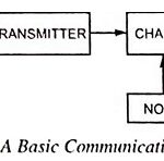
Basic Block Diagram of Communication System: The Basic Block Diagram of Communication System is shown in Fig. 22.1. The essential components of a communication system are information source, input transducer, transmitter, communication channel, receiver and destination. As already mentioned above, a communication … (Read More)
Classification of Communication: There are two basic classification of communication systems, baseband systems and passband systems. In baseband systems, the signal is transmitted without modifying the frequency content. A simple intercom is an example of this approach. Here, a microphone senses the … (Read More)
Modulation – Definition, Types and Need for Modulation: Any wave has three significant characteristics viz. amplitude, frequency and phase, and modulation is a process of impressing information to be transmitted on a high frequency wave, called the carrier wave, by changing … (Read More)
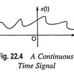
Signal Definition and Classification of Signals: A signal is a single valued function of one or more variables that conveys some information. Signals are represented mathematically as the functions of one or more independent variables. A signal may be a function … (Read More)
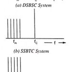
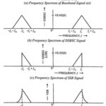
Types of Amplitude Modulation (AM): As we know already that, one carrier and two sidebands are produced in AM generation. However, it is not essential that all these signals are transmitted to enable the receiver to reconstruct the original signal. One … (Read More)
Vestigial Sideband Modulation System (VSB): A Vestigial Sideband Modulation System (VSB) is actually a compromise between DSBSC and SSB modulation systems. In other words, it can be said that it is an optimum choice in which the advantages of DSBSC and … (Read More)
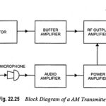
Block Diagram of AM Transmitter: Block Diagram of AM Transmitter is shown in Fig. 22.25. Sound waves produced by speech or music strike the diaphragm of a microphone that converts them into a tiny varying current. The audio frequency output of the … (Read More)
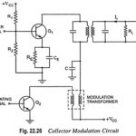
Collector Modulation Circuit – Working, Advantages and Disadvantages: This is very popular method for AM generation. The circuit diagram for collector modulation is shown in Fig. 22.26. Here, the transistor Q1 makes an RF class C amplifier. The carrier signal is … (Read More)
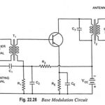
Base Modulation Circuit Working Principle: The circuit for base modulation is shown in Fig. 22.28. The carrier signal from a crystal oscillator is coupled to the base terminal of the amplifier through transformer T1. The modulating signal is applied across resistor … (Read More)
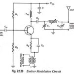
Emitter Modulation – Circuit Diagram and its Operation: The circuit for emitter modulation is shown in Fig. 22.29. It is essentially a CE amplifier. The carrier signal from a crystal oscillator is coupled to the base of amplifier through capacitor Cin. … (Read More)
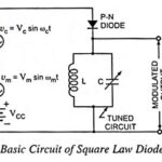
Square Law Diode Modulator – Circuit Diagram and its V-I Characteristics: Basic circuit of a square law diode modulator is shown in Fig. 22.30. It utilizes the nonlinear region of voltage-current dynamic characteristic of a P-N diode. This square law diode … (Read More)
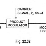
Generation of DSBSC Signal using Balanced and Ring Modulator: DSBSC signal can be obtained by simply multiplying the modulating signal with the carrier signal. By simple multiplication of Vc sin ωct and Vm sin ωmt, we have the lower and upper sidebands without carrier … (Read More)
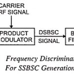
Single Sideband Modulation (SSB): Single Sideband Modulation (SSB) can he obtained by passing the output of a carrier suppressor (product modulator) through filter circuits that are selective to transmit one sideband while suppressing the other. However, this method is suitable only … (Read More)
What is Demodulation or Detection? – Need of demodulation: Demodulation or detection is a process of recovering the original modulating signal (intelligence) from the modulated carrier wave i.e., the demodulation is a process reverse of the process of modulation. Need of demodulation: The … (Read More)
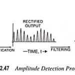
Amplitude Detection Process: Amplitude Detection – The process of demodulation demands that the modulated wave has some definite average value and the carrier wave is separated out. Hence in demodulation of an AM wave two operations, viz. rectification of the modulated … (Read More)
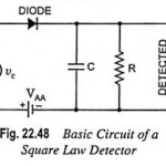
Square Law Detector Circuit and Working Principle: The square law detector circuit is used for demodulating modulated signal of small amplitude (i.e., below 1 V) so that the operating region may be restricted to the nonlinear portion of the V-I characteristics … (Read More)
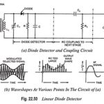
Linear Diode Detector or Envelope Detector: Diode detection is called the envelope detection as it recovers the audio frequency signal envelope from the composite signal. Diode detector is also called the linear detector as its output is proportional to the voltage … (Read More)
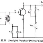
Transistor Detector Circuit Working Principle: It is possible to achieve amplitude demodulation by using a three-element electronic device. A typical example of such a configuration is illustrated in Fig. 22.51. This circuit is called a transistor detector. In addition to detection of … (Read More)
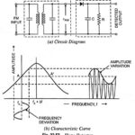
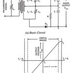
Simple Slope Detector – Circuit diagram and its Characteristics: The circuit diagram of a simple slope detector is depicted in Fig. 22.52(a). This Slope Detector circuit consists of a tuned circuit which is slightly detuned from the carrier frequency ωc. In … (Read More)
Balanced Slope Detector – Working, Advantages and Disadvantages: The circuit of a balanced slope detector is shown in Fig. 22.53 (a). This circuit employees two slope detectors connected back to back to the opposite ends of a centre tapped secondary of … (Read More)
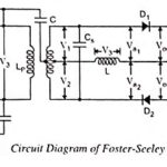
Foster Seeley Detector – Circuit Diagram, Working and its Phasor Diagram: The circuit diagram of the Foster Seeley detector is shown in Fig. 22.54. This Foster Seeley Detector circuit consists of an inductively coupled double tuned circuit in which both primary … (Read More)
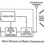
Radio Communication System – Block Diagram and types: Radio communication is very popular technique of communicating a message. The radio waves are electromagnetic waves produced due to escape of electrical energy into free space. They have a frequency range from a … (Read More)