Motor Control Articles:
Motor Control by Static Power Converters: Motor Control by Static Power Converters – Power electronics is a multidisciplinary technology that encompasses power semiconductor devices, converter circuits, electric machines, signal electronics, control theory, microcomputers, very-large scale integration (VLSI) circuits, computer-aided design techniques, … (Read More)
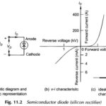
What is Semiconductor Diode? The Semiconductor Diode (Silicon Rectifier) described here in Fig 11.2(a) are based on the property of p-type and n-type materials in conjunction. An ideal diode presents zero impedance to current flow in one direction and infinite impedance … (Read More)
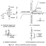
What is Silicon Controlled Rectifier (SCR)? | Construction and Working of SCR: What is Silicon Controlled Rectifier (SCR)? – This semiconductor switching device is also known as a thyristor. It is a 4-layer, 3-junction, bistable (ON and OFF) semiconductor switch. The … (Read More)
What is Power Transistor? | Definition | Working | Applications: What is Power Transistor? – Power Transistors are now available in ratings suitable for motor control. This device is a 3-layer p-n-p (or n-p-n) structure, as shown in Fig. 11.5. This … (Read More)
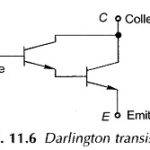
Darlington Transistor Working: A Darlington-connected transistor pair is shown in Fig. 11.6. The current gain of the power transistor can be considerably improved if the base drive current is obtained from another transistor. This is called a … (Read More)
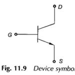
What is Power MOSFET? The power metal oxide semiconductor field-effect transistor (MOSFET) is a device derived from the field effect transistor (FET) for use as a fast-acting switch at power levels. Unlike the bipolar transistor which … (Read More)
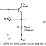
Insulated Gate Bipolar Transistor (IGBT): An Insulated Gate Bipolar Transistor (IGBT) is basically a hybrid MOS-gated turn on/off bipolar transistor that combines the features of MOSFET (voltage control features), BJT (fast acting features and high power capability) and thyristor. The device … (Read More)
Static Induction Transistor (SIT) | Symbol | Features: An Static Induction Transistor (SIT) is a high-power high-frequency device and is essentially the solid state version of triode vacuum tube. It was commercially introduced by Tokin Corp, Japan, in 1987. The device … (Read More)
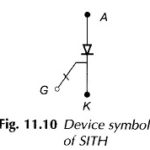
Static Induction Thyristor (SITH) – Symbol and its Workings: An Static Induction Thyristor (SITH) or SI-thyristor is a self-controlled GTO-like on-off device commercially introduced in Japan in 1988. Similar device, known as field-controlled thyristors (FCT) or field-controlled diode (FCD), were developed … (Read More)
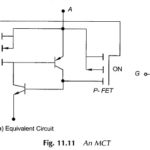
MOS Controlled Thyristor (MCT) | Symbol | Equivalent Circuit: An MOS Controlled Thyristor (MCT) is a thyristor-like trigger-into-conduction device that can be turned on or off by a short pulse on the MOS gate. It is a high power, high frequency, … (Read More)
Recent Trends in Power Semiconductors: The recent trends in Power Semiconductors from application point of view show that MOSFETs and IGBTs are replacing BJTs almost completely while GTOs are currently being used for high V and power ratings (> 0.5 MVA), … (Read More)
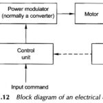
Block Diagram of Electrical Drives | Advantages | Applications: Block Diagram of Electrical Drives – Invention of thyristor led to emergence of semiconductor drives in early sixties. The improvements in converters and development of new drive-control strategies, such as field oriented … (Read More)
What is Power Electronic Converter? Since the introduction of the thyristor, the Power Electronic Converter technology has progressed through intense technological evolution for the last four decades and has emerged into a multidisciplinary technology. With basic … (Read More)
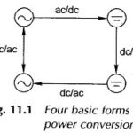
Types of Converters in Power Electronics: The different types of converters in power electronics are AC/DC Converters AC/AC Converters The Matrix Converter DC/DC Converters DC/AC Converters Control VSI Current Source Inverters (CSI) AC/DC Converters: AC DC Converters – The naturally commutated phase-controlled converter is a common type of controlled power electronic … (Read More)
Thyristor Control of Motors: A variety of thyristor control circuitry has been devised for use in motor control depending upon the type of supply (ac/dc) and the type and size of the motor. For dc motor control, … (Read More)
DC Motor Control through Converters: DC motor control is conveniently and efficiently achieved by phase-controlled converters wherein the ac input voltage is converted to a controlled dc output. The commutation process, the transfer of current from one thyristor to the other, in … (Read More)
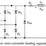
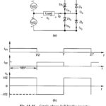
Three Phase Semi Converter feeding Separately Excited DC Motor: Large-kW motors are fed from 3-phase supply through three Phase Converters. In a three Phase Semi Converter, the ripple frequency of the motor terminal voltage is higher than that in the single-phase … (Read More)
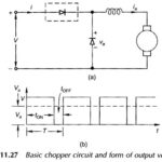
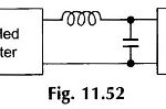
Basic Principle of Chopper Circuit: A Basic Principle of Chopper Circuit is essentially a thyristor switch in series with the load as shown in Fig. 11.27(a). A shunting diode is provided across the load for free-wheeling the load current when the … (Read More)
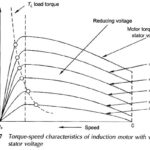
Induction Motor Speed Control Methods: The only way to control the speed of a synchronous motor is to control the input frequency and voltage such as to keep V/f constant. The Induction Motor Speed Control, on the other hand, can be … (Read More)
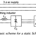
Static Scherbius Drive Circuit Diagram: A basic scheme of a Static Scherbius Drive Circuit Diagram converter cascade, that is employed for recovery of slip power in electrical form itself, is given in Fig. 11.42. For achieving both subsynchronous and supersynchronous speed control, … (Read More)
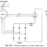
Static Kramer Drive: The Static Kramer drive system which consists of variable-speed drive system shown in Fig. 11.43 consists of a slipring induction motor and a rectifier-fed dc motor. The machines are connected electrically in cascade. The slip power recovery takes place … (Read More)
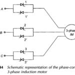
Phase Control of Three Phase Induction Motor: Figure 11.44 shows the schematic representation of Phase Control of Three Phase Induction Motor. Two thyristors are connected in antiparallel in each line. The firing sequence of the thyristors for all modes of operation … (Read More)
Single Phase Half Bridge Inverter | R Load | RL Load | RLC Load: Figure 11.46(a) gives the circuit configuration of a Single Phase Half Bridge Inverter. It has two thyristors and two free-wheeling diodes. Each thyristor is gated at frequency … (Read More)
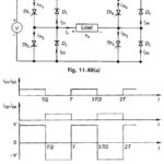
Single Phase Bridge Inverter: A serious disadvantage of the half-Bridge Inverter of Fig. 11.46 is that it requires a 3-wire dc supply. This is overcome by the commonly employed Single Phase Bridge Inverter circuit of Fig. 11.48(a) which needs four thyristors and … (Read More)
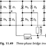
Three Phase Bridge Inverter | Working Principle: The basic three phase bridge inverter is a six-step inverter. A step is defined as a change in the firing sequence. A 3-phase thyristor bridge-inverter is shown in Fig. 11.49. Th1 to Th6 are … (Read More)
 Voltage and Harmonic Control of Inverters: In applying Inverters for motor control both V and f (keeping V/f constant) need to be varied. Further, the inverters apply essentially nonsinusoidal ac voltage to the motor. External … (Read More)
What is PWM Inverter? In presenting the arguments here attention will be focused on a single-phase inverter. Instead of the single rectangular pulse output of Figs 11.46 and 11.48 during each half-cycle, a commutation circuitry can … (Read More)
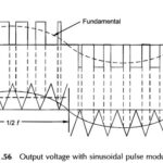
What is Sinusoidal Pulse Width Modulation? In Sinusoidal Pulse Width Modulation the pulse-width instead of being uniform as in the waveform of Fig. 11.55 is a sinusoidal function of its angular position with respect to a reference sine wave resulting in … (Read More)
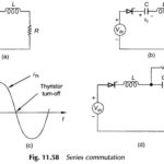
Types of Forced Commutation: It was observed from the discussion on choppers and inverters that in thyristor systems fed from dc supply, the forward current does not pass through zero naturally and must therefore be forced to become zero at appropriate … (Read More)
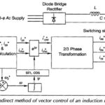
Vector Control of Induction Motor: The sole idea behind the vector control of induction motor is to have an electrical drive which must offer superior performance than widely used separately excited dc motor in industry. Further such a drive should also … (Read More)
What is TRIAC? | Symbolic Representation | VI Characteristics of TRIAC: What is TRIAC? – The full form of TRIAC is Triode for Alternating Current (TRIAC) or Triode for AC. It is a bilateral switch with three terminals—anode, cathode and a … (Read More)
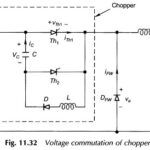
Voltage Commutated Chopper Circuit: This Voltage Commutated Chopper Circuit comprises an auxiliary thyristor Th2, a diode D, inductor L and capacitor C as shown in Fig. 11.32 wherein the total chopper circuitry has been outlined with a dotted box. To start the … (Read More)
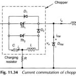
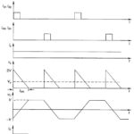
Current Commutated Chopper Circuit: Figure 11.34 shows a Current Commutated Chopper Circuit. The main thyristor Th1 of the chopper is commutated by a current pulse generated in the commutation circuitry. The sequence of operation is given below, and various significant waveforms … (Read More)
Load Commutated Chopper Circuit: In this method of Load Commutated Chopper Circuit, the load current flowing through the thyristor is made to become zero while the motor current is conducted by the free-wheeling diode. Figure 10.36(a) shows the circuit of a … (Read More)