Multistage Amplifiers Articles:
What is Multistage Amplifier? – Types, Block Diagram and Analysis Amplifiers that produce voltage, current, and/or power gain through the use of two or more stages are called multistage amplifiers. It may be emphasized here that a practical amplifier is always … (Read More)
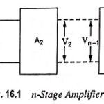
n Stage Cascaded Amplifier: As already discussed, several amplifier stages are usually cascaded to increase the overall voltage gain of the amplifier. However, sometimes cascading is done to obtain the desired output and input impedance for specific applications. Block diagram of … (Read More)
Frequency Response of RC Coupled Amplifier: The curve drawn between the voltage gain and signal frequency of an amplifier is known as the frequency response. The performance of an frequency response of RC coupled amplifier is judged to a considerable extent … (Read More)
Step Response of an Amplifier: An alternative criterion of amplifier fidelity is the response of the amplifier to a particular input waveform. Of all possible available waveforms, the most generally useful is the step voltage. In terms of a circuit’s Step … (Read More)
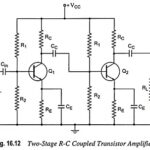
RC Coupled Transistor Amplifier – Operations, Derivation and Applications: A two-stage RC Coupled Transistor Amplifier using N-P-N transistors in CE configuration is shown in Fig. 16.12. The two transistors used are identical and use a common power supply VCC. The resistors R1, … (Read More)
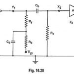
What is Low Frequency Compensation? The coupling or blocking capacitor tilts the amplifier response for step input. In Fig. 16.28, if a high value of resistance Rd is added in series with RC which connects to the supply voltage and bypass … (Read More)
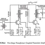
Transformer Coupled Transistor Amplifier – Working Principle: The main cause for low voltage and power gains of an R-C coupled amplifier is that the effective load (Rac) of each stage is reduced due to the low impedance presented by the input … (Read More)
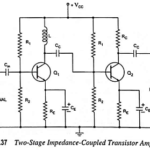
Impedance Coupled Transistor Amplifier: A two-stage impedance coupled transistor amplifier using N-P-N transistors in CE configuration is shown in Fig. 16.37. The only difference between this circuit and R-C coupled transistor amplifier circuit is that collector resistance RC of first transistor … (Read More)
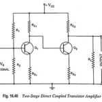
Direct Coupled Transistor Amplifier – Operations and Equivalent Circuit: Direct coupling is essential for very low frequency (below 10 Hz) applications such as photoelectric current, thermocouple current etc. Thermocouples are used for measurement of temperature in furnaces. The voltage induced in … (Read More)
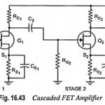
Cascaded FET Amplifier Circuit Diagram: The circuit diagram of a cascaded FET amplifier is depicted in Fig. 16.43. The overall gain of the cascaded amplifier is given by the product of stage gains Av1 and Av2. The input impedance of the cascaded amplifier, The … (Read More)
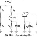
Cascode Amplifier or CE-CB Configuration: The CE-CB configuration (usually referred to as cascode amplifier) is shown in Fig. 16.44. Figure 16.44 shows a cascode configuration with a common-emitter (CE) stage feeding a common-base (CB) stage. This configuration of course, has basically … (Read More)