Nodal Analysis Examples:
Nodal Analysis Examples – we discussed simple circuits containing only two nodes, including the reference node. In general, in a N node circuit, one of the nodes is chosen as reference or datum node, then it is possible to write N — 1 Nodal Analysis Examples by assuming N — 1 node voltages. For example, a 10 node circuit requires nine unknown voltages and nine equations. Each node in a circuit can be assigned a number or a letter. The node voltage is the voltage of a given node with respect to one particular node, called the reference node, which we assume at zero potential. In the circuit shown in Fig. 2.35, node 3 is assumed as the reference node. The voltage at node 1 is the voltage at that node with respect to node 3. Similarly, the voltage at node 2 is the voltage at that node with respect to node 3. Applying Kirchhoff s current law at node 1; the current entering is equal to the current leaving. (See Fig. 2.36).
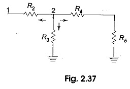
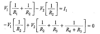
where V1 and V2 are the voltages at node 1 and 2, respectively. Similarly, at node 2, the current entering is equal to the current leaving as shown in Fig. 2.37. 
 Rearranging the above equations, we have
From the above equations, we can find the voltages at each node.
Nodal Equations by Inspection Method
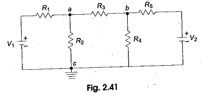
The Nodal Analysis Examples for a general planar network can also be written by inspection, without going through the detailed steps. Consider a three node resistive network, including the reference node, as shown in Fig. 2.41.
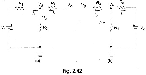
In Fig. 2.41, the points a and b are the actual nodes and c is the reference node. Now consider the nodes a and b separately as shown in Fig. 2.42 (a) and (b).
In Fig. 2.42 (a), according to Kirchhoff s current law, we have
Fig. 2.42 (b), if we apply Kirchhoffs current law, we get
Rearranging the above equations, we get
In general, the above equations can written as
By comparing Eqs 2.42, 2.43 and Eqs 2.44, 2.45 we have the self conductance at node a, Gaa= (1/R1+1/R2+1/R3) is the sum of the conductances connected to node a. Similarly, Gbb=(1/R3+1/R4+1/R5), is the sum of the conductances connected to node b. Gab=(-1/R3), is the sum of the mutual conductances connected to node a and node b. Here all the mutual conductances have negative signs. Similarly, Gba=(-1/R3) is also a mutual conductance connected between nodes b and a. I1 and I2 are the sum of the source currents at node a and node b, respectively. The current which drives into the node has positive sign, while the current that drives away from the node has negative sign.


