Non Linear Wave Shaping Articles:
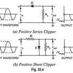
What is Clipper Circuit? – Definition and Classification: Clipper Circuit is one which controls the shape of the waveform by removing or “clipping” off an unwanted portion. A half-wave rectifier is an example of the simplest form of clipper as it … (Read More)
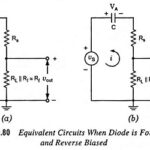
Diode Clipping Circuit – Types and Applications: Diode Clipping Circuit – For a clipping circuit at least two components—an ideal diode and resistor are required and sometimes a dc battery is also employed for fixing the clipping level. The diode acts … (Read More)
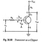
Transistor Clipper Circuit and Waveforms: Transistor Clipper Circuit – The transistor has two pronounced nonlinearities—one occurs when the transistor passes from cutin region to the active region and the second occurs when it passes from active region to the saturation region. … (Read More)
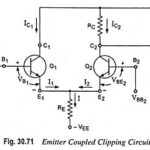
Emitter Coupled Clipper Circuit: An emitter coupled clipper using two transistors is shown in Fig. 30.71. It is a two level clipper in which the input is applied to the base of one of the transistors and the base of the … (Read More)
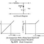
What is Comparator in Electronics? – Classification and Applications: A circuit used to mark the instant when an arbitrary waveform attains some particular reference level is called a comparator. The clipping circuits can also be used to perform the operation of … (Read More)
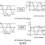
Diode Clamping Circuit – Positive and Negative Clamping: Diode Clamping Circuit – A circuit that places either the +ve or -ve peak of a signal at a desired level is known as a clamping circuit. It simply adds or subtracts a … (Read More)
Clamping Circuit Theorem: Under steady-state conditions, for any input waveform, the shape of the output waveform of a clamping circuit is fixed and also the area in the forward direction and the area in the reverse direction are related. According to … (Read More)
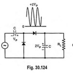
Peak to Peak Detector – Working Principle and Applications: A half-wave rectifier with a capacitor-input filter provides a dc output voltage roughly equal to the peak of the input signal. The same circuit with a small-signal diode is known as a … (Read More)
Time Base Generator – Working Principle and Types: Time base is an axis, normally X-axis, that is used to represent time so that variations of quantities such as voltages, currents etc., or their waveforms can be plotted w.r.t. time. Most of … (Read More)
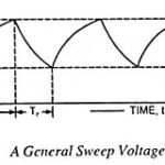
Methods of Sweep Voltage Generation: It is not possible to achieve precise linearity in sweep voltages by electronic means, various methods of sweep voltage generation are enumerated below. 1. Exponential Charging: In this method of time-base waveform generation, a capacitor is charged … (Read More)
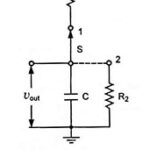
Sawtooth Voltage Generator Circuit Diagram and Waveforms: Figure 30.129 represents a basic sawtooth voltage generator. Switch S periodically changes its position from point 1 to point 2 (although a mechanical switch is shown in the circuit, the switching action is actually … (Read More)
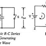
Miller Sweep Circuit and Miller Bootstrap Sweep Circuit: The basic R-C sweep circuit is shown in Fig. 30.134, in which opening of switch S provides sweep voltage, as already explained earlier. The waveform generated by this basic circuit is not exactly … (Read More)
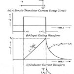
Transistor Current Sweep Circuit: A simple transistor current sweep circuit is given in Fig. 30.143 (a). In the circuit the transistor is employed as an electronic switch and the inductor in series with the transistor is bridged across the supply voltage … (Read More)
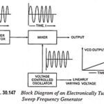
Sweep Frequency Generator – Block Diagram and its Workings: A Sweep Frequency Generator is a special type of signal generator which generates a sinusoidal output whose frequency is automatically varied or swept between two selected frequencies. One complete cycle of the frequency … (Read More)
