Operating Modes of Pentium Processor:
The Pentium processor architecture supports three Operating Modes of Pentium Processor such as protected mode, real-address mode and System Management Mode (SMM) and one ‘quasi-operating mode’ or virtual-8086 mode. In this section, all Operating Modes of Pentium Processor are explained in detail.
Protected Mode The protected mode is the local operating mode of the processor. In this mode, all instructions and architectural features are available; the processor is able to provide the highest performance capability.
Real-address Mode The real-address operating modes of Pentium Processor provides the programming environment of the 8086 processor incorporating the ability to switch to the protected mode or system management mode.
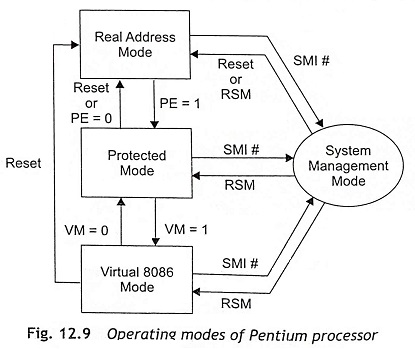
System Management Mode (SMM) The system management mode of the Pentium processor provides an operating system with a transparent mechanism for implementing power management. When an external system interrupt pin (SMI#) is activated, a System Management Interrupt (SMI) is generated and the processor has to be entered in the system management mode. In this mode, the processor switches to a separate address space while saving the context of the currently running program or task. Then the system management mode’s specific code can be executed transparently. Upon returning from SMM, the processor can be back to the real-address-mode state, or protected-mode state or virtual 8086 mode state from the system management mode by using RESET or RSM signal.
Virtual-8086 Mode When the processor operates in protected mode, it can support a quasi-operating mode known as virtual 8086 mode. This mode allows the processor to execute 8086 software in a protected as well as multitasking environment.
Figure 12.9 shows how the processor changes the operating modes. Initially, the Pentium processor enters the real-address mode through a power-up or a reset operation. After that, the PE flag in the control register CR0 controls whether the processor is in real-address or protected mode. The switching between real-address mode and protected mode requires some initialization before the mode is changed. When PE = 1, the processor operating mode changes from real address mode to protected mode.
The VM flag in the EFLAGS register decides whether the processor will be operated in protected mode or virtual 8086 mode. The transitions from protected mode to virtual 8086 mode are generally carried out as part of a task switch or a return from an interrupt or exception handler. When VM = 1, the processor-operating mode changes from protected mode to virtual 8086 mode
Real Mode
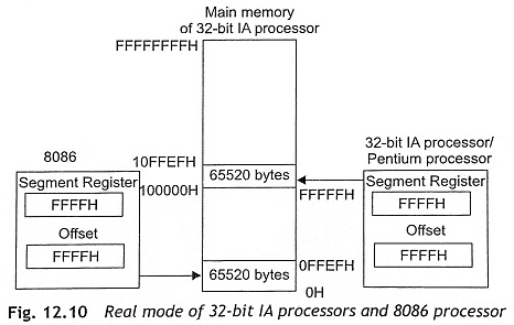
The Pentium processor can support real mode for backward compatibility with the 8086 microprocessor. In real mode, the processor computes the physical addresses from the content of CS and IP registers just like the 8086. But the difference is that while the 8086 had a 20-bit adder, the Pentium processors have a 32-bit adder. Therefore, in real mode, the IA processors can address over 1 MB with a 21-bit address bus. Hence in real mode, the only extra memory that is available from 100000H to 10FFEFH cannot be used in full 21-bit address. Figure 12.10 shows the real-mode operation of 32-bit IA processors. The physical address computation is given below when the content of segment register is FFFFH and offset is equal to FFFFH.
In case of 8086, the leading ‘1’ will be lost as a carry and the address that appears on the 20-bit address bus is 0FFEFH. This is a case of wrap around. In the 32-bit IA/Pentium processors, the address that appears is 10FFEFH. Consequently, in real mode, Pentium processor can access addresses greater than 1 MB causing a pseudo-protection exception and software interrupt.
Protected Mode
The protected-mode operation of the Pentium processor protects different tasks in multitasking operating systems from invalid accesses. The processor hardware checks all accesses of a program to code and data and provides access rights based on four different privilege levels. Task switching is very fast in protected mode.
Memory Management of Pentium During protected-mode operation of the Pentium processor, memory management is done in two different ways, namely, segmentation and paging.
- Segmentation Segmentation issued to isolate individual code, data, and stack modules so that multiple programs can run on the same processor without interfering with other programs.
- Paging Paging is one of the memory management techniques which allows the processor to address a range of virtual memory that is greater than the physical memory that can be addressed using the processor’s address bus alone. This is done by swapping pages in and out of the main memory and on and off the disk.
In protected mode, segmentation cannot be disabled but the use of paging is optional.
Actually, segmentation divides the processor’s addressable memory space into small protected address spaces called segments. This address space is also known as the linear address space. Usually, segments are used to hold the code, data, and stack for a program or it can also hold system data. Whenever more than one program is executed on a processor, each program must be assigned its own set of segments. Then the processor enforces the boundaries between these segments so that one program does not interfere with the execution of other programs.
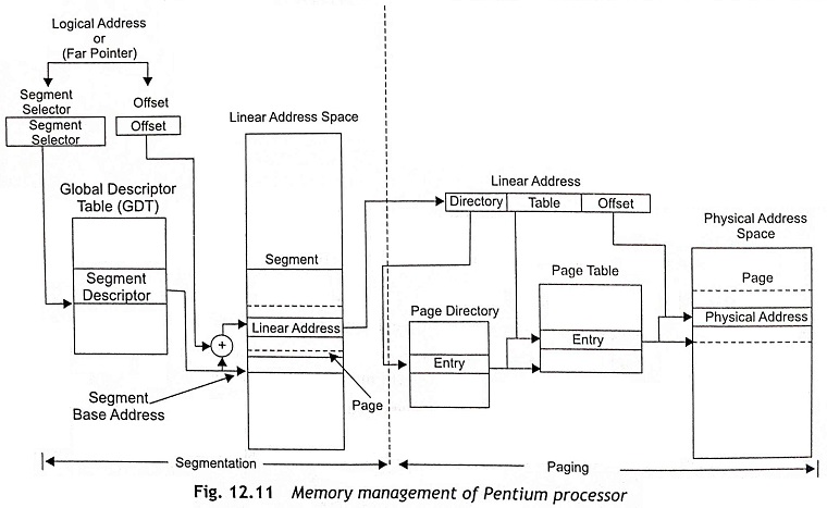
All segments must be exist in the processor’s linear address space. The logical address is used to locate a byte in a particular segment. The logical address is also called a far pointer. Figure 12.11 shows the memory management of a Pentium processor in protected mode. It is clear from Fig. 12.11 that the logical address consists of a segment selector and an offset.
Each segment has a unique segment selector and it provides an offset into the Global Descriptor Table (GDT) to a data structure called a segment descriptor. The segment descriptor is used to specify the size of the segment, the access rights and privilege level for the segment, the segment type, and the location of the first byte of the segment in the linear address space which is known as the base address of the segment. The offset part of the logical address or far pointer must be added to the base address of the segment and generates an address to locate a byte within the segment. In this way, the addition of base address and the offset determines a linear address in the Pentium processor’s linear address space as depicted in Fig. 12.11.
When the paging technique is not used in memory management, the linear address space of the processor is mapped directly into the physical address space of the processor. Then the physical address space can be described as the range of addresses that the Pentium processor can generate on its address bus.
When the paging technique is used, IA-32 bit Pentium processors have a linear address space. A linear address is stored in the linear address space. Actually, the linear address consists of page directory, page table and offset. The physical address is computed by using the contents of page directory, page table and offset to locate a memory location in the physical memory as depicted in Fig. 12.11. In fact, paging supports a ‘virtual memory’ environment where a large linear address space is replicated with a small size of physical memory, which is either RAM or ROM or disk storage. With application of paging, each segment must be divided into pages and each page size is about 4 Kbytes, which can be stored either in physical memory or on the disk.


