Operational Amplifier Frequency Response Articles:
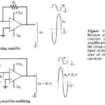
Operational Amplifier Circuit Stability: Loop Gain and Loop Phase Shift – Consider the inverting amplifier circuit and waveforms in Fig. 15-1(a). The signal voltage voltage (vs) is amplified by a factor R2/R1, and phase shifted through -180°. The Operational Amplifier Circuit … (Read More)
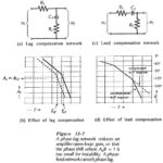
Frequency Compensation Methods: Phase-Lag and Phase-Lead Compensation – Lag compensation and lead compensation are two Frequency Compensation Methods often employed to stabilize op-amp circuits. The phase-lag network in Fig. 15-7(a) introduces additional phase lag at some low frequency where the op-amp … (Read More)
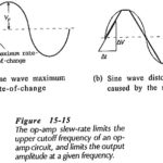
Op Amp Circuit Bandwidth and Slew Rate Test: Low Cutoff Frequency – Op Amp Circuit Bandwidth and Slew Rate Test are direct-coupled internally, so where they are employed in direct-coupled applications, the circuit lower cutoff frequency (f1) is zero. In capacitor-coupled … (Read More)
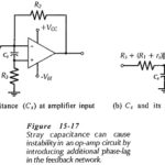
Stray Capacitance Effects: Stray Capacitance Effects (Cs) at the input terminals of an operational amplifier effectively introduces an additional phase-lag network in the feedback loop, (see Fig. 15-17), thus making the op-amp circuit unstable. Stray capacitance problems can be avoided by good … (Read More)
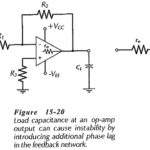
Load Capacitance Effect: Capacitance connected at the output of an operational amplifier is termed Load Capacitance Effect (CL). Figure 15-20 shows that CL is in series with the op-amp output resistance (ro), so CL and ro constitute a phase-lag circuit in the … (Read More)
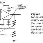
Circuit Stability Precautions: Power Supply Decoupling – Feedback along supply lines is another source of op-amp circuit instability. This can be minimized by connecting 0.01 μF high-frequency capacitors from each supply terminal to ground (see Fig. 15-23). The capacitors must be … (Read More)