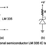
Potentiometric Recorder Working Principle (Multipoint)

Potentiometric Recorder Working Principle (Multipoint): Potentiometric Recorder Working Principle - The thermocouple or millivolt signal is amplified by a non-inverting MOSFET, chopper stabilized, feedback amplifier. This configuration has a very…

Continue Reading Potentiometric Recorder Working Principle (Multipoint)

Function Generator Block Diagram

Function Generator Block Diagram: A Function Generator Block Diagram produces different waveforms of adjustable frequency. The common output waveforms are the sine, square, triangular and sawtooth waves. The frequency may…

Continue Reading Function Generator Block Diagram

Digital Readout Oscilloscope

Digital Readout Oscilloscope: The Digital Readout Oscilloscope instrument has a CRT display and a counter display. The diagram shown is of an instrument where the counter measures the time (Fig.…

Continue Reading Digital Readout Oscilloscope

What is Sampling Oscilloscope?

What is Sampling Oscilloscope?: An ordinary Sampling Oscilloscope has a B.W. of 10 MHz. The HF performance can be improved by means of sampling the input waveform and reconstructing its…

Continue Reading What is Sampling Oscilloscope?

Trigger Pulse Generator Circuit

Trigger Pulse Generator Circuit: The Trigger Pulse Generator Circuit is activated by signals of a variety of shapes and amplitudes, which are converted to trigger pulses of uniform amplitude for…

Continue Reading Trigger Pulse Generator Circuit

Automation in Digital Instruments

Automation in Digital Instruments: Automation in Digital Instruments - One of the advantages of digital multimeters is their ease of operation. The reading is easy to take and does not…

Continue Reading Automation in Digital Instruments

Microprocessor Based Ramp Type DVM

Microprocessor Based Ramp Type DVM: A basic block diagram of a Microprocessor Based Ramp Type DVM and its operating waveform is shown in Fig. 5.17 (a) and (b) respectively. Depending…

Continue Reading Microprocessor Based Ramp Type DVM

Continuous Balance DVM

Continuous Balance DVM: Continuous Balance DVM - The basic block diagram of a servo balancing potentiometer type DVM is shown in Fig. 5.15. The input voltage is applied to one…

Continue Reading Continuous Balance DVM