Cascaded FET Amplifier Circuit Diagram
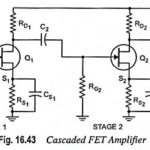
Cascaded FET Amplifier Circuit Diagram: The circuit diagram of a cascaded FET amplifier is depicted in Fig. 16.43. The overall gain of the cascaded amplifier is given by the product…
Direct Coupled Transistor Amplifier - Operations and Equivalent Circuit: Direct coupling is essential for very low frequency (below 10 Hz) applications such as photoelectric current, thermocouple current etc. Thermocouples are…
Impedance Coupled Transistor Amplifier: A two-stage impedance coupled transistor amplifier using N-P-N transistors in CE configuration is shown in Fig. 16.37. The only difference between this circuit and R-C coupled…
Transformer Coupled Transistor Amplifier - Working Principle: The main cause for low voltage and power gains of an R-C coupled amplifier is that the effective load (Rac) of each stage…
RC Coupled Transistor Amplifier - Operations, Derivation and Applications: A two-stage RC Coupled Transistor Amplifier using N-P-N transistors in CE configuration is shown in Fig. 16.12. The two transistors used are…
Step Response of an Amplifier: An alternative criterion of amplifier fidelity is the response of the amplifier to a particular input waveform. Of all possible available waveforms, the most generally…
Frequency Response of RC Coupled Amplifier: The curve drawn between the voltage gain and signal frequency of an amplifier is known as the frequency response. The performance of an frequency…
n Stage Cascaded Amplifier: As already discussed, several amplifier stages are usually cascaded to increase the overall voltage gain of the amplifier. However, sometimes cascading is done to obtain the…