Potentiometric Recorder Working Principle (Multipoint)

Potentiometric Recorder Working Principle (Multipoint): Potentiometric Recorder Working Principle - The thermocouple or millivolt signal is amplified by a non-inverting MOSFET, chopper stabilized, feedback amplifier. This configuration has a very…
Continue Reading Potentiometric Recorder Working Principle (Multipoint)

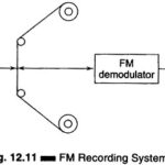
Frequency Modulation Recording

Frequency Modulation Recording: When a more accurate response to dc voltages is required, an Frequency Modulation Recording system is generally used. In this FM system, the input signal is used…

Continue Reading Frequency Modulation Recording

XY Recorder Working

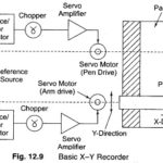
XY Recorder Working: XY Recorder Working - In most research fields, it is often convenient to plot the instantaneous relationship between two variables [Y = f(x)], rather than to plot…

Continue Reading XY Recorder Working

Null Type Recorder Working Principle

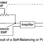
Null Type Recorder: These Null Type Recorder Working Principle of self-balancing or null conditions. When an input is given to the measuring circuit of the recorder from a sensor or transducer,…

Continue Reading Null Type Recorder Working Principle

Strip Chart Recorder Working Principle

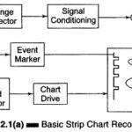
Strip Chart Recorder Working Principle: Strip Chart Recorder Working Principle are those in which data is recorded on a continuous roll of chart paper moving at a constant speed. The…

Continue Reading Strip Chart Recorder Working Principle

Definition of Recorder

Definition of Recorder: Definition of Recorder - A recorder is a measuring instrument that displays a time-varying signal in a form easy to examine, even after the original signal has ceased…

Continue Reading Definition of Recorder

Detectors Types

Detectors Types: The Detectors Types are as follows For low frequency, the most convenient detector is the vibration galvanometer. For ordinary laboratory work at frequencies up to a few 100 Hz,…

Continue Reading Detectors Types

Wien Bridge Circuit Diagram

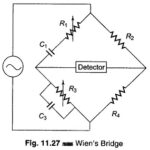
Wien Bridge Circuit Diagram: The Wien Bridge Circuit Diagram shown in Fig. 11.27 has a series RC combination in one arm and a parallel combination in the adjoining arm. Wien's…

Continue Reading Wien Bridge Circuit Diagram