Differential Amplifier Circuit Operation
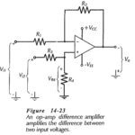
Differential Amplifier Circuit Operation: A Differential Amplifier Circuit Operation amplifies the difference between two inputs. The circuit shown in Fig. 14-23 is a combination of inverting and noninverting amplifiers. Resistors…
Continue Reading
Differential Amplifier Circuit Operation