Classification of Transmission Lines
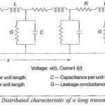
Classification of Transmission Lines: Classification of Transmission Lines are usually classified as Lines with no loss or ideal lines, Lines without distortion or distortion less lines Lines with small losses,…
Travelling Waves on Transmission Lines: Any disturbance on a Travelling Waves on Transmission Lines or system such as sudden opening or closing of line, a short circuit or a fault…
Mathematical Model of Lightning Stroke: During the charge formation process, the cloud may be considered to be a nonconductor. Hence, various potentials may be assumed at different parts of the…
Impulse measurements using Multiple Shield Enclosures and Signal Cable: Multiple Shield Enclosures - It is essential that leads, layout, and connections from the signal sources to the CRO are to be…
Rogowski Coil Integrator Design: If a Rogowski Coil Integrator Design is placed surrounding a current carrying conductor, the voltage signal induced in the coil is vi(t) = M dI(t)/dt where…
Low Ohmic Shunt: The most common method employed for high impulse current measurements is a Low Ohmic Shunt shown in Fig. 7.46. The equivalent circuit is shown in Fig. 7.46b.…
Measurement of High Direct Current: High magnitude direct currents are measured using a resistive shunt of low ohmic value. The voltage drop across the resistance is measured with a millivoltmeter.…
Peak Reading Voltmeter Circuit: Sometimes it is enough if the Peak Reading Voltmeter Circuit of an impulse voltage wave is measured; its waveshape might already be known or fixed by…