Gear Wheel Method for Frequency Measurement

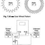
Gear Wheel Method for Frequency Measurement: When a Lissajous figure contains a large number of loops, accurate counting becomes difficult. Figure 7.35 shows a test method that uses a modulated…

Continue Reading Gear Wheel Method for Frequency Measurement

Spot Wheel Method for Frequency Measurement

Spot Wheel Method for Frequency Measurement: As the ratio of the two frequencies being compared increases, the Lissajous pattern becomes more complicated and hence more difficult to interpret. In such…

Continue Reading Spot Wheel Method for Frequency Measurement

Dual Trace Oscilloscope

Dual Trace Oscilloscope: Figure 7.19 (a) shows a block diagram of Dual Trace Oscilloscope. This CRO has a single electron gun whose electron beam is split into two by an…

Continue Reading Dual Trace Oscilloscope

Trigger Pulse Generator Circuit

Trigger Pulse Generator Circuit: The Trigger Pulse Generator Circuit is activated by signals of a variety of shapes and amplitudes, which are converted to trigger pulses of uniform amplitude for…

Continue Reading Trigger Pulse Generator Circuit

Horizontal Deflection System in CRO

Horizontal Deflection System in CRO: The Horizontal Deflection System in CRO consist of a Time Base Generator and an output amplifier. Sweep or Time Base Generator: A continuous sweep CRO…

Continue Reading Horizontal Deflection System in CRO

Block Diagram of CRO

Block Diagram of CRO: The Basic Block Diagram of CRO is shown in Fig.7.5. The ac filament supplies power to the CRT heaters in the Block Diagram of CRO. This…

Continue Reading Block Diagram of CRO

Block Diagram of Oscilloscope

Block Diagram of Oscilloscope: The major Block Diagram of Oscilloscope shown in Fig. 7.4, of a general purpose CRO, is as follows: CRT Vertical amplifier Delay line Time base Horizontal…

Continue Reading Block Diagram of Oscilloscope