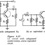
CE Circuit with Unbypassed Emitter Resistor
CE Circuit with Unbypassed Emitter Resistor: h-parameter Equivalent Circuit - When an CE Circuit with Unbypassed Emitter Resistor (RE) as shown in Fig. 6-25(a), it is also present in the…
Continue Reading
CE Circuit with Unbypassed Emitter Resistor