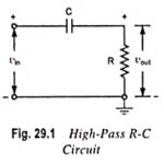
RC High Pass Circuit as Differentiator
RC High Pass Circuit as Differentiator: RC High Pass Circuit as Differentiator - A circuit that gives an output voltage proportional to the derivative of its input, is known as…
Continue Reading
RC High Pass Circuit as Differentiator