IC Controller for Switching Regulators

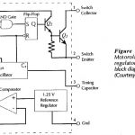
IC Controller for Switching Regulators: The functional block diagram of a MC34063 integrated circuit controller is shown in Fig. 17-38. This IC is designed to be used as a variable…

Continue Reading IC Controller for Switching Regulators

Oscillator Amplitude Stabilization Circuit

Oscillator Amplitude Stabilization Circuit: Output Amplitude - For all of the Oscillator Amplitude Stabilization Circuit discussed, the output voltage amplitude is determined by the amplifier maximum output swing. The output…

Continue Reading Oscillator Amplitude Stabilization Circuit

Parallel Current Negative Feedback Circuit

Parallel Current Negative Feedback Circuit: Current Feedback Circuit - In series-voltage feedback, a portion of the output voltage is fed back in series with the signal source. In Parallel Current…

Continue Reading Parallel Current Negative Feedback Circuit

Amplifier Testing

Amplifier Testing: Preparation - Transistor Amplifier Testing and other circuits should be tested in a methodical fashion; otherwise the results obtained may be useless. The circuit should first be carefully…

Continue Reading Amplifier Testing

FET and BJT Difference

FET and BJT Difference: FET and BJT Difference (CS, CD, and CG Circuit Comparison) - Table 11-1 compares Zi, Zo and Av for CS, CD, and CG circuits. As already discussed, the…

Continue Reading FET and BJT Difference

Common Source Circuit Analysis

Common Source Circuit Analysis: A FET Common Source Circuit Analysis is shown in Fig. 11-­6. With the capacitors treated as ac short-circuits, the circuit input terminals are the gate and…

Continue Reading Common Source Circuit Analysis

FET Equivalent Circuit Model

FET Equivalent Circuit Model: The complete FET Equivalent Circuit Model is shown in Fig. 11-5(a). It is seen that tilt source terminal is common to both input and out, so…

Continue Reading FET Equivalent Circuit Model