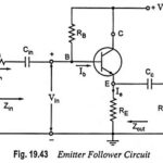
Cascode Amplifier or CE-CB Configuration

Cascode Amplifier or CE-CB Configuration: The CE-CB configuration (usually referred to as cascode amplifier) is shown in Fig. 16.44. Figure 16.44 shows a cascode configuration with a common-emitter (CE) stage…

Continue Reading Cascode Amplifier or CE-CB Configuration

Low Frequency Response of FET Amplifier

Low Frequency Response of FET Amplifier: The analysis of the Low Frequency Response of FET Amplifier is quite similar to that of the BJT amplifier. Though here common-source configuration is…

Continue Reading Low Frequency Response of FET Amplifier

Low Frequency Response of BJT Amplifier

Low Frequency Response of BJT Amplifier: For analysis, we will consider the loaded voltage-divider BJT bias configuration. But the results can be applied to any configuration. For the network shown…

Continue Reading Low Frequency Response of BJT Amplifier

Emitter Bias Circuit Diagram

Emitter Bias Circuit Diagram: This Emitter Bias Circuit Diagram is obtained by simply introducing an emitter resistor to the fixed bias circuit as shown in Fig. 12.9. For analysis, we…

Continue Reading Emitter Bias Circuit Diagram