Low Pass Filter Circuits
Low Pass Filter Circuits: The Low Pass Filter Circuits of Fig. 15.7 is commonly used for low pass active filters. The filtering is done by the use of an RC…
Continue Reading
Low Pass Filter Circuits
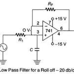
Low Pass Filter Circuits: The Low Pass Filter Circuits of Fig. 15.7 is commonly used for low pass active filters. The filtering is done by the use of an RC…
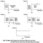
Types of Filters in Electronics: Types of filters in electronics may be of any physical form—electrical, mechanical, pneumatic, hydraulic, acoustical, etc. The most commonly used filters are of the electrical…
What are Passive Filters?: Passive filters are mainly networks using inductors, capacitors and resistors. The classical theory employed was based on the image parameter theory which in turn was based…
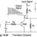
Transistor Chopper Circuit: Transistor Chopper Circuit - A single transistor used as a dynamic switch to convert low level dc signal to an ac waveform is shown in Fig. 14.34.…
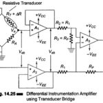
Differential Instrumentation Amplifier Transducer Bridge: Figure 14.25 shows a simplified circuit of a Differential Instrumentation Amplifier Transducer Bridge. In this circuit a resistive transducer (whose resistance changes as a function…
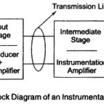
Instrumentation System Block Diagram: Instrumentation System - The measurement and control of physical conditions is very important in many industrial and consumer applications. For example, the operator may make necessary…
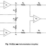
Instrumentation Amplifier Circuit: The schematic diagram of an Instrumentation Amplifier Circuit constructed with dc opamps and consisting of general features is shown in Fig. 14.23 (a). Many of the input…
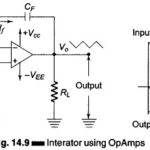
Integrator using Op Amp: An Integrator is a circuit that performs the mathematical operation of integration because it produces an output voltage that is proportional to the integral of the…