Potentiometric Recorder Working Principle (Multipoint)

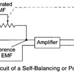
Potentiometric Recorder Working Principle (Multipoint): Potentiometric Recorder Working Principle - The thermocouple or millivolt signal is amplified by a non-inverting MOSFET, chopper stabilized, feedback amplifier. This configuration has a very…

Continue Reading Potentiometric Recorder Working Principle (Multipoint)

XY Recorder Working

XY Recorder Working: XY Recorder Working - In most research fields, it is often convenient to plot the instantaneous relationship between two variables [Y = f(x)], rather than to plot…

Continue Reading XY Recorder Working

Null Type Recorder Working Principle

Null Type Recorder: These Null Type Recorder Working Principle of self-balancing or null conditions. When an input is given to the measuring circuit of the recorder from a sensor or transducer,…

Continue Reading Null Type Recorder Working Principle

Detectors Types

Detectors Types: The Detectors Types are as follows For low frequency, the most convenient detector is the vibration galvanometer. For ordinary laboratory work at frequencies up to a few 100 Hz,…

Continue Reading Detectors Types

Wien Bridge Circuit Diagram

Wien Bridge Circuit Diagram: The Wien Bridge Circuit Diagram shown in Fig. 11.27 has a series RC combination in one arm and a parallel combination in the adjoining arm. Wien's…

Continue Reading Wien Bridge Circuit Diagram

Hays Bridge Circuit

Hays Bridge Circuit: Hays Bridge Circuit, shown in Fig. 11.23, differs from Maxwell's bridge by having a resistance R1 in series with a standard capacitor C1 instead of a parallel.…

Continue Reading Hays Bridge Circuit

Maxwell Bridge Theory

Maxwell Bridge Theory: Maxwell Bridge theory, shown in Fig. 11.21, measures an unknown inductance in terms of a known capacitor. The use of standard arm offers the advantage of compactness…

Continue Reading Maxwell Bridge Theory

Comparison Bridge

Comparison Bridge: There are two types of Comparison Bridge, Namely Capacitance Comparison Bridge Inductance Comparison Bridge 1. Capacitance Comparison Bridge: Figure 11.18 shows the circuit of a capacitance comparison bridge.…

Continue Reading Comparison Bridge