Transformer Coupled Class B Amplifier
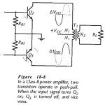
Transformer Coupled Class B Amplifier: Class B Amplifier - The inefficiency of Class-A amplifiers is largely due to the transistor bias conditions. In a Class-B amplifier, the transistors are biased…
Oscillator Amplitude Stabilization Circuit: Output Amplitude - For all of the Oscillator Amplitude Stabilization Circuit discussed, the output voltage amplitude is determined by the amplifier maximum output swing. The output…
RC Phase Shift Oscillator Circuit Diagram: Figure 16-1 shows the RC Phase Shift Oscillator Circuit Diagram, which consists of an inverting amplifier and an RC phase-shifting network. The amplifier phase-shifts…
Op Amp Circuit Bandwidth and Slew Rate Test: Low Cutoff Frequency - Op Amp Circuit Bandwidth and Slew Rate Test are direct-coupled internally, so where they are employed in direct-coupled…
Effects of Negative Feedback in Amplifiers: Decibels of Feedback - Effects of Negative Feedback in Amplifiers can be measured in decibels. A statement that 40 dB of feedback has been…
DC Motor Drives Articles: Types of DC Motor: The commonly used Types of DC Motor are shown in Fig. 5.1. In a separately excited motor, the field and armature voltages…
Power Factor Improvement Methods: There are many drives which operate at a low power factor. Some of Power Factor Improvement Methods are: An induction motor direct on line. ac-dc diode…
Stator Voltage Control of Induction Motor: By reducing Stator Voltage Control of Induction Motor, speed of a high-slip induction motor can be reduced by an amount which is sufficient for…