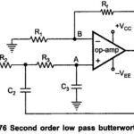
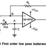
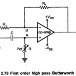
First Order Low Pass Butterworth Filter

First Order Low Pass Butterworth Filter: The first order low pass butterworth filter is realized by R-C circuit used along with an op-amp, used in the noninverting configuration. The circuit…

Continue Reading First Order Low Pass Butterworth Filter

Basic Antilog Amplifier Using Diode

Basic Antilog Amplifier Using Diode: The circuit diagram of basic antilog amplifier using diode is shown in the Fig. 2.70. The positions of diode and resistance are exchanged as compared…

Continue Reading Basic Antilog Amplifier Using Diode

Precision Full Wave Rectifier

Precision Full Wave Rectifier: The Precision Full Wave Rectifier circuits accept an ac signal at the input, inverts either the negative or the positive half, and delivers both the inverted…

Continue Reading Precision Full Wave Rectifier

Precision Rectifiers

Precision Rectifiers: Recall from basic circuit principles that a rectifier circuits can be implemented with a diode/diodes (half wave rectifier or full wave rectifier). The major limitations of these Precision…

Continue Reading Precision Rectifiers

Three Op Amp Instrumentation Amplifier

Three Op Amp Instrumentation Amplifier | Block Diagram | Advantages | Applications: The commonly used Instrumentation Amplifier circuit is one using three op amps. This Three Op Amp Instrumentation Amplifier…

Continue Reading Three Op Amp Instrumentation Amplifier

Summing Differentiator Circuit

Summing Differentiator Circuit: Summing Differentiator Circuit - Similar to the summing integrator, summing can be obtained using the basic differentiator Circuit. It can be obtained by applying more than one…

Continue Reading Summing Differentiator Circuit