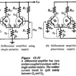
Differential Amplifier Circuit using Transistors
Differential Amplifier Circuit using Transistors: The Differential Amplifier Circuit using Transistors is widely applied in integrated circuitry, because it has both good bias stability and good voltage gain without the…
Continue Reading
Differential Amplifier Circuit using Transistors