Sample and Hold Circuit

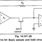
Sample and Hold Circuit: Four basic sample and hold circuit are shown in Fig. 14.141. In these circuits a JFET is used as switch. During the sampling time the JFET…

Continue Reading Sample and Hold Circuit

8279 Block Diagram

8279 Block Diagram: Fig. 14.84 shows the 8279 Block Diagram. It consists of four main sections CPU interface and control section Scan section 8279 Keyboard section Display section 1.CPU Interface…

Continue Reading 8279 Block Diagram

Interfacing 8259 with 8085

Interfacing 8259 with 8085: Fig. 14.72 shows Interfacing 8259 with 8085 microprocessor system. Addressing of 8259A : The 74LS138 address decoder will assert the CS input of the 8259A when…

Continue Reading Interfacing 8259 with 8085

8259 Block Diagram

8259 Block Diagram: Fig. 14.71 shows the internal 8259 Block Diagram. It includes eight blocks : data bus buffer, read/write logic, control logic, three registers (IRR, ISR and IMR), priority…

Continue Reading 8259 Block Diagram

Features of 8096 Microcontroller

Features of 8096 Microcontroller: Here, we are going to see 16-bit microcontroller MCS 8096. It is designed for high speed/high performance control applications. The Features of 8096 Microcontroller are namely,…

Continue Reading Features of 8096 Microcontroller

Maximum Mode Configuration of 8086

Maximum Mode Configuration of 8086: A processor is in the Maximum Mode Configuration of 8086 when its MN/MX pin is grounded. The maximum mode defines pins 24 to 31 as…

Continue Reading Maximum Mode Configuration of 8086