Thyristors Articles

Thyristors Articles: Silicon Controlled Rectifier Principle Operation: Silicon Controlled Rectifier Principle Operation (SCR) consists of four layers of semiconductor material, alternately p-type and n-type as illustrated in Fig. 19-1(a). Because…

Continue Reading Thyristors Articles

Photodarlington Working

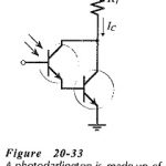
Photodarlington Working: The Photodarlington Working shown in (Fig. 20-33) consists of a phototransistor connected in Darlington arrangement with another transistor. This device is capable of producing much higher output currents…

Continue Reading Photodarlington Working

Silicon Bilateral Switch

Silicon Bilateral Switch: It might be convenient to think of a Silicon Bilateral Switch (SBS) as an SUS with a gate terminal, or as a low-current TRIAC. However, the SBS is…

Continue Reading Silicon Bilateral Switch

Silicon Unilateral Switch

Silicon Unilateral Switch: The Silicon Unilateral Switch (SUS), also known as a four layer diode and as a Schokley diode, can be treated as a low-current SCR without a gate…

Continue Reading Silicon Unilateral Switch

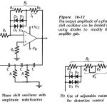
Oscillator Amplitude Stabilization Circuit

Oscillator Amplitude Stabilization Circuit: Output Amplitude - For all of the Oscillator Amplitude Stabilization Circuit discussed, the output voltage amplitude is determined by the amplifier maximum output swing. The output…

Continue Reading Oscillator Amplitude Stabilization Circuit

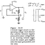
Schmitt Trigger Circuit Diagram

Schmitt Trigger Circuit Diagram: Inverting Schmitt Trigger - A Schmitt Trigger Circuit Diagram is a fast-operating voltage level detector. When the input voltage arrives at a level determined by the…

Continue Reading Schmitt Trigger Circuit Diagram

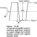
Voltage Level Detectors

Voltage Level Detectors: Voltage Level Detectors - Operational amplifiers are often used in circuits in which the output is switched between the positive and negative saturation voltages, +Vo(sat) and -+Vo(sat). The…

Continue Reading Voltage Level Detectors

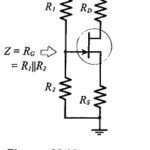
FET and BJT Difference

FET and BJT Difference: FET and BJT Difference (CS, CD, and CG Circuit Comparison) - Table 11-1 compares Zi, Zo and Av for CS, CD, and CG circuits. As already discussed, the…

Continue Reading FET and BJT Difference