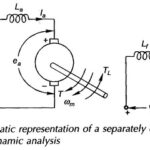
Variable Frequency Transformer

Variable Frequency Transformer | Application: So far we have considered transformers which operate at fixed frequency (50 Hz). Their purpose is to transform electric power from one voltage level to…

Continue Reading Variable Frequency Transformer

Transformer Efficiency Formula

Transformer Efficiency Formula: Power and distribution transformers are designed to operate under conditions of constant rms voltage and frequency and so the efficiency and voltage regulation are of prime importance.…

Continue Reading Transformer Efficiency Formula

Per Unit System

Per Unit System: While carrying out the analysis of electrical machines (or electrical machine systems), it is usual to express voltage, current, VA and impedance in Per Unit System (or…

Continue Reading Per Unit System

Transformer Testing Methods

Transformer Testing Methods: Two chief difficulties which do not warrant the Transformer Testing Methods by direct load test are: Large amount of energy has to be wasted in such a…

Continue Reading Transformer Testing Methods

Different types of losses in transformer

Different types of losses in transformer: The transformer has no moving parts so that its efficiency is much higher than that of rotating machines. Different types of losses in transformer…

Continue Reading Different types of losses in transformer

Phasor Diagram of Transformer

Phasor Diagram of Transformer: For the approximate equivalent circuit of Phasor Diagram of Transformer is shown in Fig. 3.16(b) The phasor diagram corresponding to this equation is drawn in Fig.…

Continue Reading Phasor Diagram of Transformer

Approximate Equivalent Circuit of Transformer

Approximate Equivalent Circuit of Transformer: Approximate Equivalent Circuit of Transformer - In constant frequency (50 Hz) power transformers, approximate forms of the exact T-circuit equivalent of the transformer are commonly…

Continue Reading Approximate Equivalent Circuit of Transformer

Real Transformer On Load Condition

Real Transformer On Load Condition | Equivalent Circuit: Figure 3.11 shows a Real Transformer On Load Condition. Both the primary and secondary have finite resistances R1 and R2 which are…

Continue Reading Real Transformer On Load Condition