Nonlinear Distortion Measurements

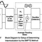
Nonlinear Distortion Measurements: One of the methods of Nonlinear Distortion Measurements consists of simulta­neously applying two sinusoidal voltages of different frequencies to the amplifier input and observing the sum, difference…

Continue Reading Nonlinear Distortion Measurements

RF UHF field strength meter circuit

RF UHF field strength meter circuit: There are two general methods available for determination of RF UHF field strength meter circuit. One is the standard antenna method. In this, use…

Continue Reading RF UHF field strength meter circuit

Introduction to Digital Filtering

Introduction to Digital Filtering: It has been seen that control of the band width of a circuit or signal is of paramount importance in optimizing the measurement of a signal.…

Continue Reading Introduction to Digital Filtering

Band Reject Filter Circuit

Band Reject Filter Circuit: In this Band Reject Filter Circuit, frequencies are attenuated in the stop band and passed outside it, as shown in Fig. 15.20(b). As with band pass…

Continue Reading Band Reject Filter Circuit

Band Pass Filter Circuit Diagram

Band Pass Filter Circuit Diagram: A Band Pass Filter Circuit Diagram designed to pass signals only in a certain band of frequencies while rejecting all signals outside this band. There…

Continue Reading Band Pass Filter Circuit Diagram

Low Pass Filter Circuits

Low Pass Filter Circuits: The Low Pass Filter Circuits of Fig. 15.7 is commonly used for low pass active filters. The filtering is done by the use of an RC…

Continue Reading Low Pass Filter Circuits

Classification of Active Filters

Classification of Active Filters: An electric filter is often a frequency selective circuit that passes a specified band of frequencies and blocks or attenuates signals of frequencies outside this band.…

Continue Reading Classification of Active Filters