Transistor as a Switch Circuit Diagram and Working
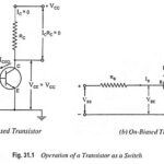
Transistor as a Switch Circuit Diagram and Working: The Transistor as a Switch Circuit Diagram and Working can be explained with the help of its output characteristics. Figure 31.2 shows…
What is Switching Circuit? In practice, we often need making (switching on) and breaking (switching off) of an electrical circuit. It is also desirable and sometimes essential that the switching…
RC Integrator Circuit Diagram and its Application: A circuit that gives an output voltage directly proportional to the integral of its input is known as integrating circuit. Figure 29.18 shows…
Low Pass RC Circuit Diagram, Derivation and Application: The Low Pass RC Circuit is shown in Fig. 29.18. In a Low Pass RC Circuit, the output voltage vout is taken…
RC High Pass Circuit as Differentiator: RC High Pass Circuit as Differentiator - A circuit that gives an output voltage proportional to the derivaÂtive of its input, is known as…
High Pass RC Circuit Diagram, Derivation and Application: The High Pass RC Circuit is shown in Fig. 29.1. The reactance of the capacitor is given as i.e., Reactance XC of…
Step up Chopper - Definition, Circuit Diagram and its Working Principle: In a step-down chopper the output voltage lies between zero and supply voltage. However, there are techniques by which…
Three Phase Converter Circuit: For large sized (rating exceeding 15 kW) motors 3-phase drive is employed. The output voltage of a 3-phase converter has less ripple contents than that of…