Voltage Doubler Circuit

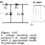
Voltage Doubler Circuit: A Voltage Doubler Circuit produces an output voltage which is approximately double the peak voltage of the input waveform. Consideration of the voltage doubler circuit diagram in…

Continue Reading Voltage Doubler Circuit

Diesel Electric Traction System

Diesel Electric Traction System: Because of high initial cost, electric traction is justified only where there is sufficient volume of traffic. Diesel Electric Traction System is preferable where the traffic…

Continue Reading Diesel Electric Traction System

Conventional DC and AC Traction Drives

Conventional DC and AC Traction Drives: The commonly used Conventional DC and AC Traction Drives are The dc Traction Drives Employing Resistance Control: The dc traction drives employing resistance control…

Continue Reading Conventional DC and AC Traction Drives

Drive Circuits for Stepper Motor

Drive Circuits for Stepper Motor: A Drive Circuits for Stepper Motor is usually driven from a low voltage dc source. When a phase is to be energised, the dc source…

Continue Reading Drive Circuits for Stepper Motor

Brushless DC Motor Drives

Brushless DC Motor Drives(Trapezoidal PMAC): The cross section of a 3-phase 2 pole Brushless DC Motor Drives is shown in Fig. 7.15. It has permanent magnet rotor with wide pole…

Continue Reading Brushless DC Motor Drives

Armature Voltage Control using Transformer

Armature Voltage Control using Transformer: Variable voltage for the dc motor control can also be obtained by either using an auto-transformer or a Armature Voltage Control using Transformer with tappings…

Continue Reading Armature Voltage Control using Transformer

Vertical Deflection Circuit in TV

Vertical Deflection Circuit in TV: The Vertical Deflection Circuit in TV include the vertical oscillator and amplifier for vertical scanning at 60 Hz and a similar horizontal arrangement for scanning…

Continue Reading Vertical Deflection Circuit in TV

Pulsed Radar System Block Diagram

Pulsed Radar System Block Diagram: A very Pulsed Radar System Block Diagram set was shown in Figure 16-1. A more detailed block diagram will now be given, and it will…

Continue Reading Pulsed Radar System Block Diagram