Logarithmic Amplifier using Diode
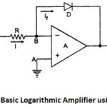
Logarithmic Amplifier using Diode: The circuit diagram of basic Logarithmic Amplifier using Diode is shown in the Fig. 2.69. The diode D is used in the negative feedback path. The…
Three Op Amp Instrumentation Amplifier | Block Diagram | Advantages | Applications: The commonly used Instrumentation Amplifier circuit is one using three op amps. This Three Op Amp Instrumentation Amplifier…
Summing Amplifier: As the input impedance of an op-amp is extremely large, more than one input signal can be applied to the inverting amplifier. Such circuit gives the addition of…
Non Inverting Operational Amplifier: An amplifier which amplifies the input without producing any phase shift between input and output is called Noninverting Amplifier. The basic circuit diagram of a Non…
Inverting Amplifier using Op Amp: Inverting Amplifier using Op Amp - As the name suggests the output of such an amplifier is inverted as compared to the input signal. The…
Operational Amplifier Applications: The countless simple circuits using one or more operational amplifiers, some external resistors and the capacitors can be constructed. Such Operational Amplifier Applications are classified as Linear…
Parameters of Operational Amplifier: Two Important Parameters of Operational Amplifier are the slew rate and the power supply rejection ratio (PSRR). Let us discuss and obtain the expressions for these…
Ideal Operational Amplifier: The Ideal Operational Amplifier is basically an amplifier which amplifies the difference between the two input signals. In its basic form, the Op Amp is nothing but…