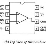
Op Amp IC 741 Pin Diagram and its Working
Op Amp IC 741 Pin Diagram and its Working: The schematic diagram and Op Amp IC 741 Pin Diagram is shown in Fig. 33.4 (a) and in Fig. 33.4 (b).…
Continue Reading
Op Amp IC 741 Pin Diagram and its Working
Op Amp IC 741 Pin Diagram and its Working: The schematic diagram and Op Amp IC 741 Pin Diagram is shown in Fig. 33.4 (a) and in Fig. 33.4 (b).…
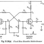
Bistable Multivibrator - Working and Types: A bistable multivibrator, as its name implies, has two stable states. It can stay in either of the two states indefinitely (as long as…
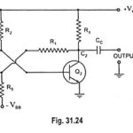
Monostable Multivibrator - Operation, Types and Application: Monostable multivibrator is a two-stage amplifier with two states—one stable state and another quasi-stable state. The circuit has two transistors Q1 and Q2,…
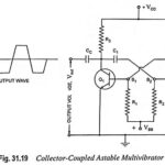
Astable Multivibrator Definition and its Working: The multivibrator circuit which has no stable state is called the astable multivibrator. The two states of operation of astable multivibrators are quasi-stable (temporary)…
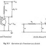
Transistor as a Switch Circuit Diagram and Working: The Transistor as a Switch Circuit Diagram and Working can be explained with the help of its output characteristics. Figure 31.2 shows…
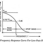
Low Pass RC Circuit Diagram, Derivation and Application: The Low Pass RC Circuit is shown in Fig. 29.18. In a Low Pass RC Circuit, the output voltage vout is taken…
High Pass RC Circuit Diagram, Derivation and Application: The High Pass RC Circuit is shown in Fig. 29.1. The reactance of the capacitor is given as i.e., Reactance XC of…
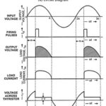
Single Phase Half Wave Controlled Rectifier with Resistive Load and Inductive Load: In a Single Phase Half Wave Controlled Rectifier only one SCR is used in the circuit. It is…