Common Collector Circuit Analysis

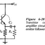
Common Collector Circuit Analysis: In the Common Collector Circuit Analysis (CC) shown in Fig. 6-28 the external load (RL) is capacitor-coupled to the transistor emitter terminal. The circuit uses voltage divider…

Continue Reading Common Collector Circuit Analysis

Current Sensing of Electrical Drives

Current Sensing of Electrical Drives: Current Sensing of Electrical Drives is required for the implementation of current limit control, inner current control loop of closed-loop speed control, closed-loop torque control…

Continue Reading Current Sensing of Electrical Drives

Surface Acoustic Waves Devices

Surface Acoustic Waves Devices(SAW): Surface Acoustic Waves Devices may be propagated on the surfaces of solid piezoelectric materials, at frequencies in the VHF and UHF regions. Devices employing SAW principles…

Continue Reading Surface Acoustic Waves Devices

Traveling Wave Tube Working

Traveling Wave Tube Working(TWT): Like the multicavity klystron, the Traveling Wave Tube Working is a linear-beam tube used as a microwave amplifier. Unlike the klystron, however, it is a device…

Continue Reading Traveling Wave Tube Working

Multicavity Klystron

Multicavity Klystron: The design of the multicavity klystron, together with all the remaining tubes described here, relies on the fact that transit time will sooner or later terminate the usefulness…

Continue Reading Multicavity Klystron

Tuned Radio Frequency Receiver

Tuned Radio Frequency Receiver: The Tuned Radio Frequency Receiver is a simple "logical" receiver. A person with just a little knowledge of communications would probably expect all radio receivers to…

Continue Reading Tuned Radio Frequency Receiver

Speed Control of DC Motor

Speed Control of DC Motor: The Fig. 15.38 shows the analog approach to control the Speed Control of DC Motor. A tachometer is used to get the information about the…

Continue Reading Speed Control of DC Motor

Sample and Hold Circuit

Sample and Hold Circuit: Four basic sample and hold circuit are shown in Fig. 14.141. In these circuits a JFET is used as switch. During the sampling time the JFET…

Continue Reading Sample and Hold Circuit