m Derived Band Pass Filter
m Derived Band Pass Filter: We can obtain m Derived Band Pass Filter if the prototype band pass filter is simplified according to the network in the Fig. 9.35 which…
Continue Reading
m Derived Band Pass Filter
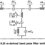
m Derived Band Pass Filter: We can obtain m Derived Band Pass Filter if the prototype band pass filter is simplified according to the network in the Fig. 9.35 which…
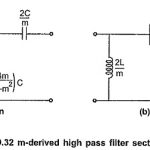
m Derived High Pass Filter: The m Derived High Pass Filter T and π sections are as shown in the Fig. 9.32 (a) and (b). Consider that the shunt arm…
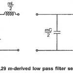
m Derived Low Pass Filter: The m Derived Low Pass Filter T and π sections are as shown in the Fig. 9.29 (a) and (b) respectively. Consider that the shunt…
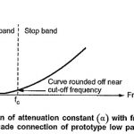
m Derived Filters: m Derived Filters - The first disadvantage of prototype filter sections can be overcome by connecting two or more prototype sections of same type (either all T…
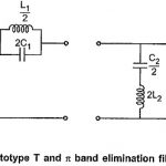
Band Stop Filter: Band Stop Filter stop a range of frequencies between two cut-off frequencies f1 and f2 while pass all the frequencies below f1 and above f2. Thus range…
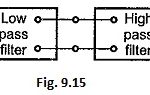
Band Pass Filter: Band pass filter pass a certain range of frequencies (called as pass band) while attenuate all other frequencies. Such band pass filters can be obtained by connecting…
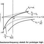
High Pass Filter: The prototype high pass filter T and π sections are as shown in the Fig. 9.9. Design Impedance (R0): Total series arm impedance Z1 = -j/ωC Total shunt…
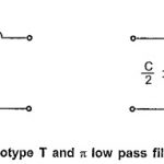
Low Pass Filter: The prototype T and π low pass filter sections are as shown in the Fig. 9.3. Design Impedance (R0): Here in low pass filter sections, Total series…