Thyristors Articles

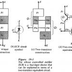
Thyristors Articles: Silicon Controlled Rectifier Principle Operation: Silicon Controlled Rectifier Principle Operation (SCR) consists of four layers of semiconductor material, alternately p-type and n-type as illustrated in Fig. 19-1(a). Because…

Continue Reading Thyristors Articles

TRIAC Control Circuit Diagram

TRIAC Control Circuit Diagram: A TRIAC Control Circuit Diagram that allows approximately 180° of phase control is shown in Fig. 19-27(a). The waveforms in Fig. 19-27(b) illustrate the circuit operation.…

Continue Reading TRIAC Control Circuit Diagram

SCR Control Circuit Diagram

SCR Control Circuit Diagram: Pulse Control - The simplest of SCR Control Circuit Diagram is shown in Fig. 19-8(a). If SCR1 was an ordinary rectifier, the ac supply voltage would…

Continue Reading SCR Control Circuit Diagram

Silicon Controlled Rectifier Principle Operation

Silicon Controlled Rectifier Principle Operation: Silicon Controlled Rectifier Principle Operation (SCR) consists of four layers of semiconductor material, alternately p-type and n-type as illustrated in Fig. 19-1(a). Because of its…

Continue Reading Silicon Controlled Rectifier Principle Operation

Voltage Level Detectors

Voltage Level Detectors: Voltage Level Detectors - Operational amplifiers are often used in circuits in which the output is switched between the positive and negative saturation voltages, +Vo(sat) and -+Vo(sat). The…

Continue Reading Voltage Level Detectors

Biasing FET Switching Circuits

Biasing FET Switching Circuits: JFET Switching - A Biasing FET Switching Circuits is normally in an off state with zero drain current, or in an on state with a very…

Continue Reading Biasing FET Switching Circuits

Clamping Circuit

Clamping Circuit: Negative and Positive Voltage Clamping Circuits - A clamping circuit, also known as a dc restorer, changes the dc voltage level of a waveform, but does not affect…

Continue Reading Clamping Circuit

Shunt Clipping Circuits

Shunt Clipping Circuits: A positive Shunt Clipping Circuits is illustrated in Fig. 3-28(a). Here the diode is connected in shunt (or parallel) with the output terminals. When the input is…

Continue Reading Shunt Clipping Circuits