Operational Amplifier Circuit Stability

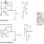
Operational Amplifier Circuit Stability: Loop Gain and Loop Phase Shift - Consider the inverting amplifier circuit and waveforms in Fig. 15-­1(a). The signal voltage voltage (vs) is amplified by a…

Continue Reading Operational Amplifier Circuit Stability

FET and BJT Difference

FET and BJT Difference: FET and BJT Difference (CS, CD, and CG Circuit Comparison) - Table 11-1 compares Zi, Zo and Av for CS, CD, and CG circuits. As already discussed, the…

Continue Reading FET and BJT Difference

Common Gate Circuit

Common Gate Circuit: The FET Common Gate Circuit (CG) shown in Fig. 11-19 uses voltage divider bias. The ac output is taken from the drain terminal, and an external load…

Continue Reading Common Gate Circuit

Common Drain Amplifier Circuit Diagram

Common Drain Amplifier Circuit Diagram: The FET Common Drain Amplifier Circuit Diagram shown in Fig. 11-14 has the output voltage developed across the source resistor (RS). The external load (RL)…

Continue Reading Common Drain Amplifier Circuit Diagram

Common Source Circuit Analysis

Common Source Circuit Analysis: A FET Common Source Circuit Analysis is shown in Fig. 11-­6. With the capacitors treated as ac short-circuits, the circuit input terminals are the gate and…

Continue Reading Common Source Circuit Analysis

BJT Cutoff Frequency and Capacitance

BJT Cutoff Frequency and Capacitance: Device Cutoff Frequency - All transistors have junction capacitances. The junction capacitances and the transit time of charge carriers through the semiconductor material limit the…

Continue Reading BJT Cutoff Frequency and Capacitance